Shunt Regulator Voltage Issue

Art Andrews

New member
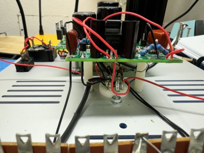
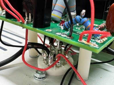
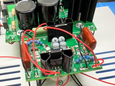
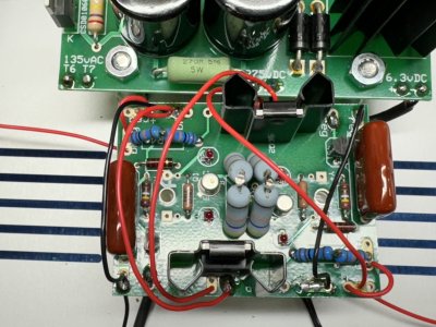
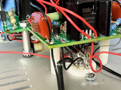
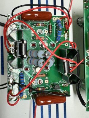
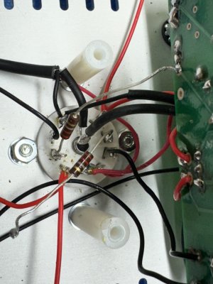
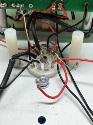
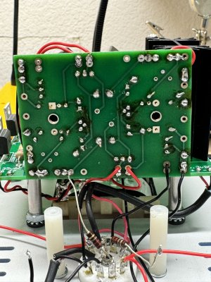
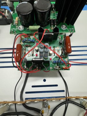
I am on page 58 of the manual and am testing the Shunt Regulator voltage.

I get the expected 300 and drop to ~225 on the red line from D1. However, on the red line from D6 I get 300 and then a drop to about ~148-140. I have revisited all the wiring but simply do not see my error. Any thoughts?


Attachments

  • IMG_6772.JPG
    IMG_6772.JPG
    627.9 KB · Views: 5
  • IMG_6773.JPG
    IMG_6773.JPG
    793.6 KB · Views: 3
  • IMG_6774.JPG
    IMG_6774.JPG
    614.9 KB · Views: 2
  • IMG_6775.JPG
    IMG_6775.JPG
    627 KB · Views: 2
  • IMG_6776.JPG
    IMG_6776.JPG
    880.1 KB · Views: 3
Looking at the instructions for making that measurement (Pg 55 of my Eros II manual), it says measure from ground post to metal tab of each MJE5731A. Why are you measuring from D1 and D6 to ... ?
 
If the 2N2907 transistors are installed against the PC board, that can cause problems. 

There are some solder joints on the PC board that also don't look 100% flowed out. 

What are your Kreg voltages?

Typically the 148V indicates unrestricted current passing to that half of the D socket, and often that is a solder bridge on the bottom side of the PC board.
 
Hi Paul,

I have detached and pulled the 2N2907 transistors up ever so slightly so they aren't sitting on the board. It is very slight but they are off it now. I also went back and tried to resolder everything and check everything. Same results.

I unsoldered a few wires to access the bottom of the board. Here is where I currently stand.

I don't know how to take Kreg Voltages. If you could assist me on what is needed, I am happy to get them.
 

Attachments

  • IMG_6819.JPG
    IMG_6819.JPG
    664.6 KB · Views: 8
  • IMG_6818.JPG
    IMG_6818.JPG
    536.9 KB · Views: 6
  • IMG_6817.JPG
    IMG_6817.JPG
    536.7 KB · Views: 8
  • IMG_6816.JPG
    IMG_6816.JPG
    836.9 KB · Views: 10
Hi Paul,

My solder gun is set to 750.

I am using Cardas Soldering Wire, which is "a blend of silver, copper, tin and lead." I was told this was quality solder for this type of project and used this same solder on my mailnine which turned out great.

It would be painful, but I could go back and unsolder everything on that board and resolder it if necessary. Or, if there are specific items you think I need to detach and reattach, I am happy to do it.
 
I would just turn your iron (hopefully not a solder gun) as high as it will go, as those joints will flow out a bit better with a hotter iron.  You can reheat all the joints except the LEDs on that board and it may help.
 
Hi Paul,

I misspoke when saying soldering gun. I have a Weller 70 watt soldering station. I believe I can get it up to 850 but I thought for boards, you were supposed to stay between 650 and 750. Will go back through at the higher temp and reheat all the joints. Given the meter reading is the issue limited to the board itself, or might there be issues elsewhere that I need to also look at?

I'd still love to get you those KREG readings, but not sure where I am placing the negative.
 
Using this photo as a guide, the KREG on the left reads 0.5 and the KREG on the right reads 5.95.
 

Attachments

  • IMG_6842.JPG
    IMG_6842.JPG
    761.7 KB · Views: 3
I would double check the resistance values of the R1 resistors on the C4S board to be sure they are correct.  Also be sure that the correct part is installed in the 431 position.
 
Back
Top