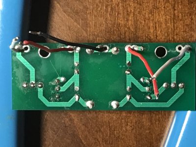
I would be looking for a broken wire. 1L is also not well soldered, but that won't cause the issue you're having.
-PB
-PB
No, there's absolutely no possibility of this. A blown cap will short, and a shorted cap will blow its insides out all over the place immediately. This will also drag your high voltage rail way, way down, and yours is still just fine.flyfisher55 said:I appreciate your knowledge in troubleshooting my build but I keep thinking that this amp was fully operational for almost a year prior to my trying the speedball upgrade. It wasn't until my hand slipped and shorted that the LED's went out. Is it possible that the 250 V capacitors would be the culprit?
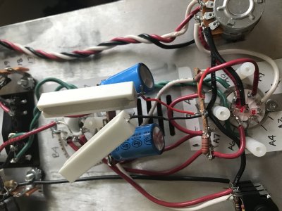
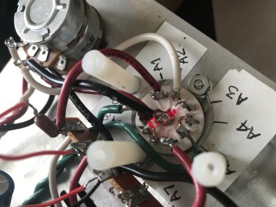
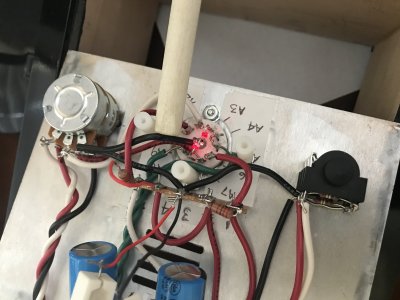
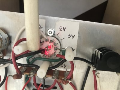
What I would suggest is getting a wooden chopstick and poking around the 9 pin socket and the small Speedball board with the amp on. You may find a spot where you can tap with your chopstick and suddenly the LED on the socket that's out lights up, and this can be used to direct your efforts.flyfisher55 said:What wires would I have to replace? Are we talking about rebuilding the entire amp?
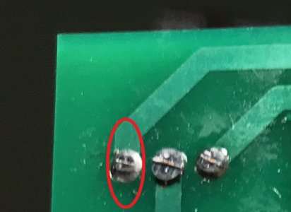
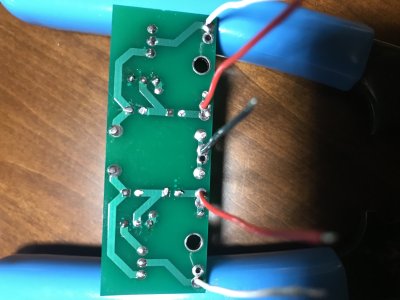
Deke609 said:Just a shot in the dark, but maybe resolder the legs of the transistor on the OB side. The circled leg looks a bit iffy in the photo (but could be perfectly fine). I'd try soldering it from the top, tinning and putting the tip on one side of the leg/trace-hole and applying solder to the other side. Might be worth a try
[/quote
Thanks Deke, I tried what you said. I've put three PN2907's into O1B. all three including original shorted one and two that I ordered read differently than O1A.
O1A L&R = O.L M Ohms
L&C =O.L M Ohms
R&C =40.19 M Ohms
O1B L&R = O.L M Ohms
L&C = O.L M Ohms
R&C =00.00 M Ohms
We use essential cookies to make this site work, and optional cookies to enhance your experience.