Scratch Build (First for me)

randy@matrixq.com

New member
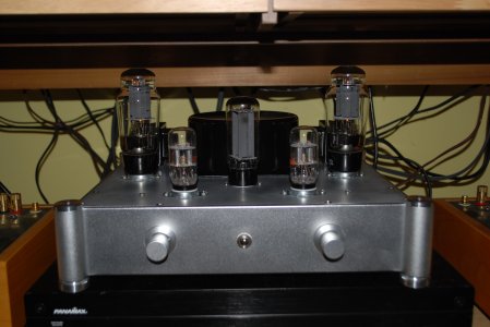
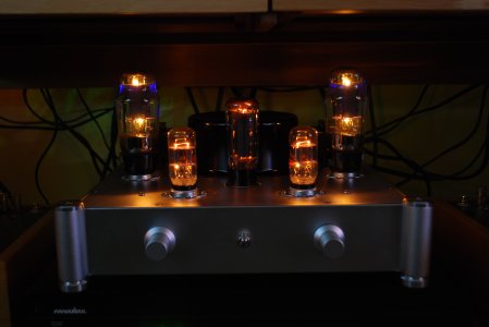
I've decided to completely rebuild an amp I had purchased before my adventures with Bottlehead.  After building 6 BH kits and buying (and examining) a few others I became disenchanted with the way this one was put together.  It is a home-built 6SL7/6L6 with a 5U4GB rectifier. 

While it was all point-to-point wired, it was done so with no terminal strips, leaving webs of resistor and capacitor leads hanging in the air.  Also, many of the components seemed under-rated which was evident when one of the capacitors blew in spectacular fashion. 

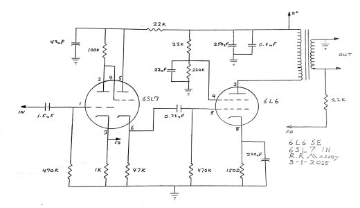
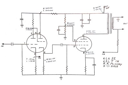
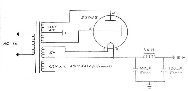
One thing led to another until I finally decided to rebuild on a whole new chassis.  The only things salvaged from the old build were the power transformer, the output transformers and the schematic.

So, before I commit to major portions of the build, I would like to run the different parts of the schematic by anyone who is interested to make sure I understand the purpose of each component.  I have a good understanding of basic electronics and I've been making a study of Morgan Jones' "Valve Amplifiers", fourth edition.  Still, questions remain.

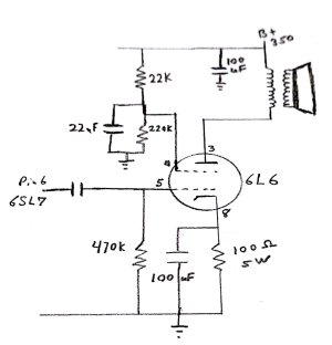
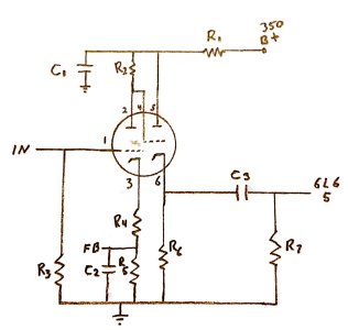
Here is the input schematic through the 6SL7.  When I purchased the amp, I was told that a 6SL7 or 6SN7 would work without modification.  I've only used 6SL7.

R1:  I understand this to be a voltage dropping resistor used to set the proper voltage on the anodes.  It is 22K in the schematic but no indication of what the proper wattage should be.

R2:  I understand this to further drop the voltage to the anode in the first stage.  It also appears to be doing double-duty in setting the grid voltage for the second stage.  It is 100K in the schematic.

C1:  This cap is 47uF in the schematic and I assume it provides further filtration of the B+ on this side of R1.

R3:  470K, I'm guessing here, but I would say it sets the input impedance and provides voltage differential for the input.

C2, R4, R5:  This part of the schematic differs from others I've seen online.  Many schematics I see simply use R4, a 1K to ground and have the feedback come in on the other side directly to pin 3.  C2 is 47uF and R5 is 300 ohms.  Is this some kind of filter?  This combination would roll off around 11 hz. 

R6:  Assuming same job as R4 in setting the voltage on the cathode.  Just for the second stage instead of the first.  47K here.

C3, R7:  Coupling capacitor to next stage.  I've seen this vary from schematic to schematic.  Mine shows 022uF, another shows 1.0uF.  I have a nice Mundorf that is .33uF that I was considering.  R7 seems to be ding what R3 did in the previous stage.

OK, that's my knowledge of tube amps so far, at least until I do some more reading.  I'm curious to hear any comments and/or suggestions.  I'm in no big hurry to finish the build.  Rather do things right and want to know why I'm doing it.

thanks,
 

Attachments

  • 6SL7 Input Stage.jpg
    6SL7 Input Stage.jpg
    237.5 KB · Views: 586
porcupunctis said:
R1:  I understand this to be a voltage dropping resistor used to set the proper voltage on the anodes.  It is 22K in the schematic but no indication of what the proper wattage should be.
That would depend massively on whether you wanted to use a 6SN7 or 6SL7 (sorry, I couldn't resist)
porcupunctis said:
R2:  I understand this to further drop the voltage to the anode in the first stage.  It also appears to be doing double-duty in setting the grid voltage for the second stage.  It is 100K in the schematic.
R2 is the plate load.  On the curves for the tube that you're using, put a dot on the voltage axis for the voltage at the junction of R2 and R1, then divide that voltage by the value of R2 to get maximum current that can be drawn through that resistor, then put a dot on the current axis.  Connect those two dots and you have a load line.  R2 should be very different for a 6SL7 vs. 6SN7.
porcupunctis said:
C1:  This cap is 47uF in the schematic and I assume it provides further filtration of the B+ on this side of R1.
Yes.
porcupunctis said:
R3:  470K, I'm guessing here, but I would say it sets the input impedance and provides voltage differential for the input.
R3 does set the input impedance.  It also serves to let some stray electrons from the grid go to ground.  If you set it too high, those electrons will create some voltage across that resistor.  If you set it to low, your preamp will hate you.
porcupunctis said:
C2, R4, R5:  This part of the schematic differs from others I've seen online.  Many schematics I see simply use R4, a 1K to ground and have the feedback come in on the other side directly to pin 3.  C2 is 47uF and R5 is 300 ohms.  Is this some kind of filter?  This combination would roll off around 11 hz. 
This is a problem with this schematic.  Feedback is generally a signal voltage sourced from the output transformer.  With C2 in its current place, you'll short that feedback voltage to ground (so it won't do anything).  Oops...
porcupunctis said:
R6:  Assuming same job as R4 in setting the voltage on the cathode.  Just for the second stage instead of the first.  47K here.
R6 has the same job as R2.
porcupunctis said:
C3, R7:  Coupling capacitor to next stage.  I've seen this vary from schematic to schematic.  Mine shows 022uF, another shows 1.0uF.  I have a nice Mundorf that is .33uF that I was considering.  R7 seems to be ding what R3 did in the previous stage.
Yeah, pretty much.  Just remember that F=1/(2*Pi*R*C), and shoot for F=5Hz.

I'd be curious to see the rest of the build.  The cathode follower driving the 6L6 is a little bit curious, as is the statement that a 6SN7 and 6SL7 will work with the same component values, as well as the feedback connection.

I'm happy to work through this with you, but I'll post outside of office hours to keep the boss happy  ;)
 
Scratch building a tube amp is a pretty challenging yet definitely worthwhile affair if one wants to learn about tube circuits.  I would highly recommend picking an old RCA Tube Manual. 

Are you particularly married to this circuit?  There are other options out there such as the old Dynaco designs which come with decades of mods and tweaks.

The nice thing about tube circuits is that they're simple and relatively forgiving.  Good luck and be careful of the high voltages!
 
If you wanted to give the 6SN7 a try, you could eliminate the cathode follower.  1/2 of a  6SN7 might be enough to drive each 6L6...John 
 
I strongly recommend not making too many changes at once. Use a known reliable circuit for your first scratch-build. Debugging a circuit you don't trust is a nightmare.
 
Wow, awesome responses, it is really appreciated.  Let me try to cover everyone in turn:

PB:  You've given me a ton of info and confirmed my suspicions.  I thought the feedback arrangement looked sketchy and will do the initial build with just the 1K to ground from pin 3 and the feedback connected directly to pin three as well.  There was a serious error in the schem for the power supply which I was able to catch before building.  This is what led me to consult some other schematics online.  I have also drawn out the 6L6 stage and will post it next. 

The feedback circuit runs from the positive (speaker side) of the Output transformer and consists of a resistor/cap in parallel.  Original schematic has 10K resistor with 103M ceramic disk cap.  Other version shows 22K with 0.01uF cap.

Right now, I have the chassis with octal sockets put together and have the power supply (5U4GB from center-tapped transformer) with CLC network. 

I'm guessing that I will need to build the circuit (both preamp and power stage) before being able to take an accurate voltage measurement between R1 and R2.  Then I can make adjustments according to the load line and curves?

PJ:  Yes, my plan is to keep the initial build as generic as possible.  I only want to deviate from the original schematic in cases where it is definitely wrong.  Like the power supply schematic that showed the DC tapped off the wrong pin of the 5U4GB.  That was wrong, dangerous and could have blown a pretty big cap by applying AC to an electrolytic.

2wo:  That sounds like an intriguing idea.  I might try that once things are stable with the amp.

corndog71:  I'm only committed to the 6SL7/6L6 combo in so much as I've purchased some nice tubes already and have the chassis built with octal sockets.  My experience with this project (which as been positive so far) will determine which direction I go with the next.  I would blame Bottlehead for this addiction to building, but I've always liked doing this sort of thing.

Again, thanks to everyone.  I will post the output schematic next.  If that passes muster, I will re-draw the entire circuit as I plan to build it initially.  Then we'll see what happens.

 
OK, here is a drawing of the output schematic.  The amp had 6L6 tubes installed when I got it and I never replaced them with anything else.  The original builder claimed the following tubes would also work:  EL34/KT77/6V6/6F6/6K6/KT88. 

I would prefer to stick with the 6L6 and optimize that option.
 

Attachments

  • 6L6 Output Schem.jpg
    6L6 Output Schem.jpg
    238.9 KB · Views: 335
I would suggest giving this design a try:

http://www.tubeaudio.8m.com/807/807.html

You'll end up needing one 9 pin socket and two octal sockets instead of the four octal sockets you have now, but it's workable.

If that design doesn't interest you, then the thing to do would be to list the power transformer and output transformer you have, then we may be able to make good suggestions. 

-PB
 
That looks intriguing, but looks better for a future project than dealing with what I have.  I would need considerable alteration to the power supply and most likely new output transformers.  Not to mention changing the sockets out for 9-pin.  I already have the octals in place.

I did find a site that shows an actual build with a very close, but less "wonky" schematic.  He actually built it, then modded it.  I think I would like to start with his initial build which is very simple and go from there.  This is more of a learning experience here.  I'm not planning on replacing my Paramounts or any other of my BH gear which I covet dearly.

Here is the link:  http://gabevee.tripod.com/setube.html

It has very few parts, and will allow me to play with some calculations to get it all "just right" and learn something in the process.  If I accomplish this without causing a fire or shutting off power to the neighborhood I will feel pretty good overall.

I will redraw a complete schematic and post before I start the final build.  I'm still waiting on a few parts, anyway.

In the meantime, I'm looking forward to drawing my first load line.
 
That one is a lot better, though I'm still laughing inside a little bit at driving a pentode with a cathode follower.  (PJ will come along here at any moment and bring up a valid reason to do this under more unusual circumstances no doubt)

Let us know how the build goes!
 
A couple of recent snow days from school has given me the opportunity to get this project together.  I can't tell you how many times I wished I had the bottlehead manual to tell me exactly how to cut the wire and where to attach it.  Laying out the parts can be a real challenge and made me appreciate what Doc and the team to for us. 

So, here's the short:  It works, and actually sounds pretty good.  Oscilloscope says that it has pretty linear response and isn't clipping unless I severely over-drive the input.  I've put in about 12 hours of listening so far and it is very pleasing.  It won't replace any of my BH amps but this was a learning exercise. 

Anyway, here are some pics.  I will post later with my measurements and a ton of questions.  Not the least of which is why PB is chuckling over the cathode follower design.

First picture is the schematic for the input and power tubes, Second and third are day and night pictures of the amp.
 

Attachments

  • 6SL7 6L6 Schematic IV.jpg
    6SL7 6L6 Schematic IV.jpg
    265.6 KB · Views: 2,054
  • Misc_209.JPG
    Misc_209.JPG
    3.1 MB · Views: 346
  • Misc_210.JPG
    Misc_210.JPG
    3 MB · Views: 198
Actually,  more like a year of ruminating and collecting parts and a few weeks of getting to the work of actually building. 

My advice to anyone thinking of a scatch build is:  Buy a nice BH kit and mod it to your hearts desire.  Unless you really like doing math and are psychotic for trial and error just move on. 

This project has been a self - induced learning lesson and the one thing I have learned is that I have a lot to learn.

Still, it is nice to create something that is all your own even if it isn't  perfect. 

I appreciate the encouragement.

 
Good job wrapping it up!

Have a listen to the amp with the junction of the 22uf/220K resistor connected to the cathode instead of ground (probably w/o the 220K resistor).  That is technically a requirement for pentode operation, and certainly an experiment that's basically free.

You should be able to dump the 1.5uF cap at the input too, though it doesn't hurt anything to leave it there.

When you get the itch to mod, come on back, we'll be here!

-PB
 
OK, my first real concern (before I do some modding) is that when I checked my voltages, it seems to be running a bit high.  For instance, Pin 5 of the 6SL7 is running just under 310 volts and the data sheet recommends a 300 volt max.  My overall B+ is 414 volts which is 50 volts over what was listed on the schematic.

Here is the schematic with voltage measurements at  points of interest:


Attachments

  • Initial Measurements.jpg
    Initial Measurements.jpg
    779.5 KB · Views: 418
Here is the schematic for the power supply.  I'm getting 414 volts for B+.  The transformer is a 365V center tap given a 120vac input.  My AC runs high at my house.  Usually around 124 to 125vac but that wouldn't seem to account for the much higher B+. 


Attachments

  • Power Supply 6SL7_6L6.jpg
    Power Supply 6SL7_6L6.jpg
    470.9 KB · Views: 156
It's typical for a cap-input filter to give 10-20% more DC voltage than the AC supplied. A higher-resistance rectifier might bring it down - 5R4? 5Y3?
 
porcupunctis said:
OK, my first real concern (before I do some modding) is that when I checked my voltages, it seems to be running a bit high.  For instance, Pin 5 of the 6SL7 is running just under 310 volts and the data sheet recommends a 300 volt max. 
That's 300V plate to cathode.  The cathode accompanying pin 5 is at about 150V, so you have 150V remaining between plate and cathode.
porcupunctis said:
My overall B+ is 414 volts which is 50 volts over what was listed on the schematic.

No biggie, you can add some resistance in the power supply if you like, but it wouldn't seem to be necessary.
porcupunctis said:
Here is the schematic with voltage measurements at  points of interest:
Nothing too out of the ordinary there.

-PB
 
I did manage to find two dusty old 5Y3 GT tubes and gave them a try.  The first one sparked internally and sounded like bacon cooking on a really hot stove.  Pulled that one and tried the other.  This one seemed to work fine and as PJ predicted lowered all my voltages.  The B+ came down to 373 (from 414) which is very close to one of the schematics I found online.

While the 5Y3 was in, I performed all the same voltage measurements as before and of course they were all lower.  There was no real change in sound quality and I seemed to notice a bit more hum at idle.  Based on PB's post, I may go back to the 5U4 rectifier.  At least I know they are both safe to try out.

PB - I would like to try the mod you suggested to the 6L6 wiring.  I won't be able to get to that until next week (Spring break) so in the meantime, I will draw up a new schematic so I can verify that I am interpreting the changes properly.  It was actually one of my future question to ask why that grid needed a voltage divider to ground while all other grids were either lifted from ground or dropped from the B+. 

Here is a question that I hope has an easy answer:  I'm running taps out for both 8 ohm and 4 ohm speakers, however the negative feedback is run off the 8 ohm taps.  Will this work as well no matter which speakers are used or do I need to set up a switch to change where the negative feedback comes from?

Thanks again for all the help (everybody), and I hope this thread is somewhat interesting and useful to other members who may be interested in knowing more about what goes on under the hood.  I know my appreciation for what BH does has grown considerably. 

 
porcupunctis said:
Here is a question that I hope has an easy answer:  I'm running taps out for both 8 ohm and 4 ohm speakers, however the negative feedback is run off the 8 ohm taps.  Will this work as well no matter which speakers are used or do I need to set up a switch to change where the negative feedback comes from?
You can leave it on the 8 Ohm tap.

 
Back
Top