S.E.X. 3.0 Kit: Right headphone driver is significantly quieter [resolved]

Jet

New member
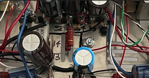
Previously I had posted about having no sound in my right headphone driver while using the S.E.X. 3.0 Kit and I got a recommendation to just touch up joints T6 and T7 of the right channel output transformer. This seems to have given me sound in right driver but upon further listening it's significantly quieter than the left.

Things I've tried:
Swapping the tubes again yet the channel imbalance doesn't follow the tubes.
Hooked up the S.E.X. 3.0 amp to a digital source and played a test tone, it made it very clear that the right driver had quite a bit more volume.
Using different RCA cables.
Different pairs of headphones.
Everything has passed resistance and voltage checks.

Thank you for the help on my previous post yet I still need some assistance.
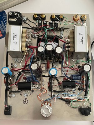
Attached is a current picture of the wiring in my kit.
 

Attachments

  • current S.E.X. 3.0 wiring.jpg
    current S.E.X. 3.0 wiring.jpg
    4.7 MB · Views: 34
Here's a joint that doesn't look soldered.

I see lots and lots of untrimmed leads.  I would get a set of side cutters (something like the CHP-170) and trim all those random leads back. 
 

Attachments

  • s3x solder joint.jpg
    s3x solder joint.jpg
    432.8 KB · Views: 33
I've cleaned up those untrimmed leads and took a look at that joint, it feels solid but I'll be sure to touch it up. While checking it out I discovered the terminal next to it (36U) looks really off up close and actually feels quite loose! I'm gonna redo everything on that terminal tomorrow.

Thanks so much for leading me in the right direction, I'll give an update once it's done. :)
 
I touched up those joints yet when I use the amplifier the left driver is still louder than the right.
Any other suggestions?
 
You might go back and redo your voltage measurements. Note any differences between channels now that you have the circuit working.
 
The resistor is at A10, it's just that you can't see it in the angle of the picture.
I did voltage checks again, everything is within the recommended values.
 
Can you post the make and model of your DVM?  We can help you send a 60Hz tone into your amp and measure it with your meter if it's sufficiently sensitive.
 
I should be able to get that exact multi-meter in the next few days, I'll give an update when I do.
 
If A9 and A8 are allowed to touch, you would get really low output, though I would expect some deviations in some of the voltages under those circumstances.
 
You can download a 60Hz test tone or use a signal generator app on a phone/tablet with a headphone output, then feed that 60Hz tone into the amp with the source device turned all the way up.

You will want to set the meter to the 2V scale and measure the AC voltage between ground and each center pin of each RCA jack, then ground and each outer (non-ground) lug of the volume pot, then each middle lug with the pot about half way up.

You should see about 0.3V going into the RCA jacks, and some attenuation of that voltage appearing at the output of the volume pot. 

None of these tests (so far) require the amp to be on, so you can get a feel for doing this without the amp on.
 
Finally got the chance to do the test, everything is around your recommended value of 0.3 AC voltage only being off by around 0.015.
 
You now need to repeat the test with the amp on but measure the AC voltage available at terminals 4 and 18 with the volume pot turned all the way up.  This voltage will be substantial enough that you'll want to be on the 20V scale.

If those are equal, then check 3 vs. 17. 

If those are equal, then check each of the positive binding posts.

At least one of those checks with yield and imbalance.  I have them listed in order so that once you find the imbalance, you can stop and we can debug, as all of the following steps will continue to show an imbalance. 
 
Before trying the next test you recommended I decided to repeat the previous one with the 60Hz tone and without voltage, I'm now getting 0.575-ish volts AC with a small fluctuation in the thousandths decimal place. Would this indicate the issue with my amp? What's causing this?
 
Terminals 4 and 18 were around 8.30 AC with some variation around 0.01 and 0.04 AC volts on the 20 volt scale.
Terminal 3 was about 16.6 AC with some variation around 0.01 and 0.09 volts AC on the 20 volt scale. At terminal 17 I had to switch to the 200 volt scale to get a reading and it was around 157 volts AC with some variation of about 0.1 to 0.6.
 
This narrows things down a bit.  Seeing the same voltage coming out of 4 and 18 tells us that the first amplification stages are working properly on each channel.

The 10x lower voltage is a bit puzzling on the second stage.  You could get a pretty big difference if the 1000uF cap on that side wasn't well connected, but not that much of a difference.  I think the next test I would do is to temporarily remove the white wire attached to terminal 10 on the output transformer of that side, then recheck the voltage at terminal 3.  We would generally expect this voltage to rise a bit with that wire disconnected, but if it pops up to 150+ volts AC, that would be helpful information.  If the voltage at terminal 3 doesn't change with that wire disconnected, then there's a bad solder joint around that socket or an untrimmed lead possibly touching the chassis or a neighboring terminal that is not allowing the signal to reach the output transformer.
 
Back
Top