Right channel noisy. Help troubleshooting

Great, thanks. So I won’t need to replace the right channel resistor to match?

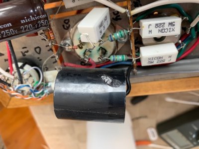
Here’s the cap I nicked. Will this be a problem?

Actually, I have a pair of Solen 3.30uF/700V and another pair of Solen 0.10uF 630V caps. I forget where these were supposed to go (and without the manual this is hard to tell). I assume the former could replace the nicked cap and its pair? And the other would go on the PC board where the Daytons are?
 

Attachments

  • IMG_2083.jpg
    IMG_2083.jpg
    88.2 KB · Views: 30
I would replace that Solen, yes.  You do not need to replace the other 2K resistor, as I said before, these are almost entirely out of the signal path.

I would do the least possible amount of messing around until you get the amp up and running properly again.  If you go to put the 0.1uF Solen caps on the regulator board and that modification causes new problems, it will make debugging a lot more difficult. 
 
OK, but just to confirm (sorry, again, I don’t have the manual on me), the 3.3uF would go to where that nicked cap is?

I’ll wait off on the regular board cap upgrade.
 
Paul Birkeland said:
If you twist the melted cap over, it should say 3.3uF on it, and yes, that's where that part goes.
Sorry, I have Clarity Caps here and the markings have faded.

Thanks for all your help! I’ll report back when I get the replacement resistor in Tuesday.
 
I was hoping to get the manual first, but Dan accidentally sent me the manual for the filament upgrade. While I’m waiting I’ll just check the voltages anyway. Which of the ones listed above are off? Maybe I can compare to that list and post just the problem readings.
 
A1.  56.8
A2. 366
A3. [no reading]
A4. 57

B1. 51.4
B2. [no reading]
B3. 51.6
B4. 51.6

Clearly there’s a problem.

I was over hasty and added those new caps after the resistance checked out. So that’s most likely where the problem is. I can put the Daytons back if you think that will help.

The one terminal with an off reading is 14, which has 301
 
The 4 pin socket readings you have at B would have me wondering if that tube is properly installed, but at the same time seeing 366 and A2 tells me that you haven't done this on the B socket, but rather you likely need to remeasure. 

The [no reading] should be around 0V, and 0V is a reading.
 
Pin 2 is the plate and will carry the high voltage.  Pin 3 is the grid and will be approximately at 0V.
 

Attachments

  • UX4 socket.gif
    UX4 socket.gif
    2.1 KB · Views: 1
Back
Top