[RESOLVED] Up in Smoke (resistor between 44L and 30L)

WK3K

New member
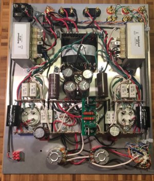
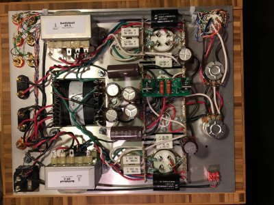
Completed a new build and resistance checks. Resistance between 8U and 8U was 1.4ohm by my (cheap) meter, so I used this as my "0" value. All resistance values were within normal limits.

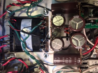
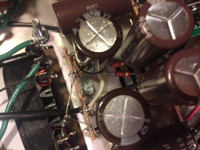
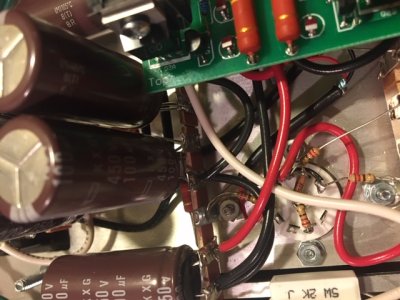
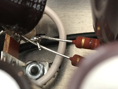
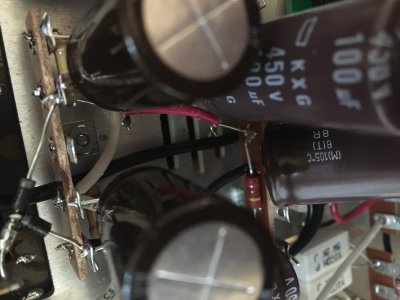
Moved on to check voltage and upon plug-in the resistor between 44L and 30L sparked and smoked. I immediately pulled the plug.

I just re-ran the resistance checks, and everything checks out with the exception of 26, 28, and 29 which are now measuring around 2.3-2.6 ohm (after the resistor blew). These were all WNL last night.

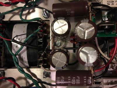
I've taken a look at the solder joints throughout the high voltage supply (and everywhere really) and don't see any glaring issues.

The only other thing I can think of is that I initially installed the MJE5731A's backward and had to pull them and reinstall. They seemed fine, but may have been damaged in the process?

Never had a snag like this during a build, so any advice on where to start trouble shooting appreciated.

Thanks!
 
I am recalling from memory, but is that one of the 130 ohm resistors? In the PS, right? If you can’t get those ASAP I have a bunch of those. Let me know. I can send you several, but check for shorts. I blew up one of those when voltage checking my second SII build. It happens.

Jamie
 
Thanks Jamie. Yes, the 130 ohm 2 watt resistors. I measured the rest of them in the power supply and they’re ok, but the one that blew is shot. I’ll got back through the circuit and double check for shorts. I didn’t see anything when I took a look yesterday, but I’ll pull out the magnifying glass. Thanks for the offer to send reinforcements, I shot you a PM.
 
Please post some photos of your build. I suspect you either have a backwards power supply cap or you have the fat pins on one or both of the 2A3s plugged into the wrong holes in the 4 pin socket.  You have to push pretty hard to get the tube to fit in like this, but it is ultimately possible to force the tube in, then you'll start blowing resistors.

-PB
 
Hi PB,

I double checked the items you suggested.
  • Caps are all oriented correctly.
  • I checked the pins on the 2A3's multiple times as this point is emphasized quite well in the manual. I even checked them again when I removed them after the resistor popped and they were 100% oriented correctly (fat pins to the back). The tubes installed easily.

EDIT: Was able to get images uploaded. Originals were apparently too large.

Thanks,
Witold
 

Attachments

  • IMG_1214.jpg
    IMG_1214.jpg
    138.2 KB · Views: 22
  • IMG_1221.JPG
    IMG_1221.JPG
    128.2 KB · Views: 16
  • IMG_1222.JPG
    IMG_1222.JPG
    110 KB · Views: 11
  • IMG_1223.JPG
    IMG_1223.JPG
    122.4 KB · Views: 13
Witold.
Look from all sides for wires that are touching.
There must be something shorted (to ground) that causes the excess current draw.

Maybe redo resistance checks now, to see if anything has changed?
 
Hi Tom,

Thanks for the advice. Just looked at everything again. The resistor to B7 *might* have been touching B8, but that's the only thing I saw. I decided just to reflow each terminal to be doubly sure there were no cold joints.

I redid resistance checks — this time 8U to 8U was exactly 1.0 so I'm using that as my "0" value (previously was 1.4 - I'm guessing this is just a meter thing). Either way, every terminal was within 1-2% of it's value with all "0" values right at 1.0.
 
Witold,

    Did you PM me? Where do I look for that? My personal email or somewhere on this forum? It may just be the perspective of the photo but the resistor (so possibly the lead) in question looks pretty close to the can(and possibly the leads) of that 100uF cap and possibly the leads of the preceding 220uF cap.

Jamie
 
The image size thing is something we need to work on.  Could you try uploading a top shot that isn't reduced by so much? 

With the 130 ohm resistor that got hot, are its leads touching any metal that they wouldn't otherwise be connected to? 

After an inspection of the overhead shot with more resolution, I can provide you with some steps to split the circuit in half to see which half is causing your issues. 

-PB
 
Image upload size has been set to unlimited for a long time. There a lots of 6MP and larger images being posted on a regular basis, as witnessed in people saying they are huge when they open them in the Chrome browser (requiring opening them in a new tab). I believe the actual issue may be trying to load multiple images into a single post, but there is no way to control that in the forum admin control panel. Anyway, it's a bug of the forum software.
 
My computer takes a little time to load pics in the 3mb and higher res, but if someone links photos to imgur I can see the page but the pics are solid black. Rats.
 
Hey all. First off, thanks for everyone jumping in and helping on a Saturday.

Jamie: I think the PM should go to the email that you have associated with your forum account. If you click "Profile" you'll see a little envelope where members can send you a note. Same thing if you click another member's profile. I'm pretty sure it's a perspective thing in the photo as the resistor goes down to the lower terminals and the caps are perched on the top of the upper terminals. There's a good gap there IRL.

PJ: I see no contacts on the blown resistor other than 270K resistor that shares 44L, the 130 resistor that shares 30L, and the 130 resistor that goes from 44L to 31L. The 130 ohm resistor that shares 44L and goes to 31L is just fine, so that might provide a clue?

Doc: Understand the limitations. I'll give it another go with images. I tried some single photos at full size and they produced the same error. Maybe it was just a timeout? I'll give it another try. [EDIT: worked to post one at a time by posting the text first and then "modifying" the post and adding attachments 1 by 1]
 

Attachments

  • IMG_1224.JPG
    IMG_1224.JPG
    3 MB · Views: 15
  • IMG_1225.JPG
    IMG_1225.JPG
    2.4 MB · Views: 6
  • IMG_1226.JPG
    IMG_1226.JPG
    1.9 MB · Views: 6
Could have been a timeout. Our webhost has been staving off DDoS attacks the past week and there have been some short service interruptions.
 
Witold,

    I did not get your email. Try emailing me from your email providers webpage. I emailed you this AM from the forum's member page, did you get that? My correct email is the one that appears on the members page in this forum. If that doesn't work we will figure something else out to get you those resistors. Don't post your personal info directly in this thread! You probably know that already though.

Also, when you remove the bad resistor consider clipping the leads with plenty of length so you can create a hook on the lead to attach the new resistor to. This will leave the solder joint at the terminal strip undisturbed and anything else that is connected to it. I think the bleeders are connected there, I don't remember exactly.Also, clear this with PB. I did this when i replaced my blown 130/2W and it worked out well, but maybe he feels differently about this. I attached a photo of my repaired
130/2W.

Jamie
 

Attachments

  • IMG_7546.jpg
    IMG_7546.jpg
    856.7 KB · Views: 23
Hey Jamie,

I didn't get your email either — even checked spam, made sure my forum account was allowing mail, etc.... I tried to resend again (I discovered the actual email isn't displayed to other members, just the link to the form), so fingers crossed something gets through. I'll give it 24 hours and see if it shakes its way through the internet. If not, I'll try to send a note by raven or owl or smoke signals.

I like the idea on the hook for the resistor — it will be tough to work under all those caps and 44L is a little crowded with that 270K resistor in addition to the 130's. I'll let PB add his two cents, but that will certainly make it easier if (heaven forbid) it blows again.
 
I did this on both ends,actually, because the other side connects to the second 130/2W which has the 90 degree bent leads. Just wanted to be clear about that. I found that this approach reduced the complexity of the repair for me. PB does this stuff all the time so his skill set and confidence level may take him a different direction but, yes, get his approval before you do it.
Also, if you connect your components with solid mechanical connection, as Doc advises, this hook approach makes it a lot easier as unsoldering those locked on bent leads is almost impossible, at least for me.

Jamie
 
Our webhost has been fending off DDoS attacks and there has been some discontinuity of service here and there for a few minutes. That may have something to do with messages not getting through.
 
OK, two connections leave terminal 27 to use the high voltage B+ feed.  One goes to the plate choke, the other goes to the C4S board. 

I would start by popping the red wire off terminal 27 that goes to the C4S board, then run the amp with no 2A3.  You can monitor the voltage at terminal 27 as you power the amp up, it should be about 390V and just kind of sit there. 

If you blew that 130 ohm resistor the point where it's open and no longer a resistor, you can temporarily install a piece of wire in its place. 

 
PB,

I removed the red wire at 27L and replaced the blown resistor with a piece of wire.

Without the 2A3 tubes installed, I powered the amp on and got 0.0v at 27. Half of each of the 12AT7's lit up (the side closest to the center of the amp).

Thanks, Witold
 
PB - looks like the resistor from 30L to 27L is blown too. No resistance or conductivity across it.

[EDIT] That resistor is sitting very close to the terminal strip and it looks like it could have possibly contacted the ground buss at 29L. I don't see contact, but it is tight in there and is the closest place where I could see accidental contact occurring.

W
 

Attachments

  • IMG_1237.JPG
    IMG_1237.JPG
    2.1 MB · Views: 13
Back
Top