[resolved] Crack + SB Woes. Left Channel dies after 5 minutes

Blue

New member
Hi There,

After my Crack and Speed Ball has been working for 2 weeks, it has decided to exhibit some problems.
The left channel dies out after about 5 minutes of usage (you can hear it very barely). Before it dies, the left channel will have some loud static, then it pops and dies.
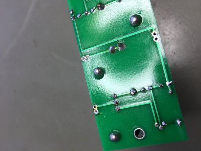
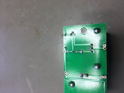
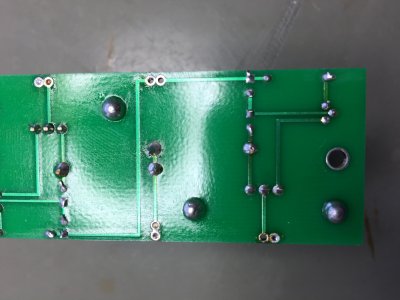
I resoldered all the joints on the tube sockets and the the OA transistor on the bigboard.
I tapped on all the solder joints, and no popping sounds come from it, so I think the solder joints on the terminals and sockets are good.

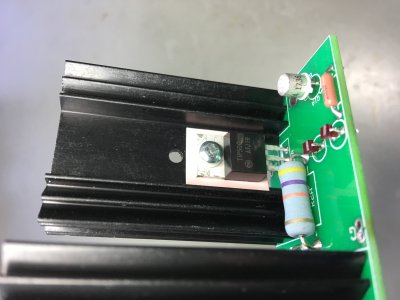
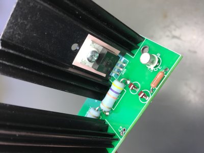
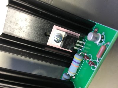
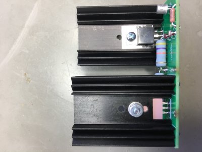
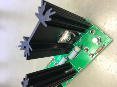
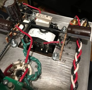
When the left channel dies out, the LED closest to the transistor at OA on the big board stops glowing.
I also measured the temperatures at some points.
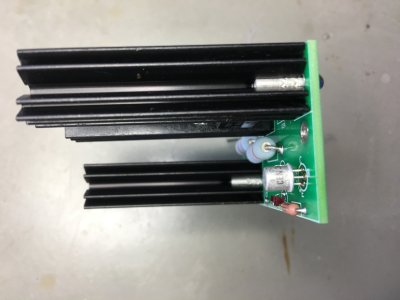
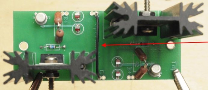
The white ceramic resistors by the transformers are anywhere between 120-150 degrees Celsius when the left channel dies.
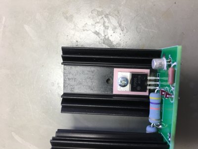
The transistor at OA on the bigboard is between 63-79 degrees., while the transistor at OB is at 47 degrees.

Once i let it cool off, and turn it on again, it works again for 5 minutes before the left channel fails again.
In those 5 minutes the voltages are correct.

One thing I noticed is when the left channel dies, the temperature sky rises on the mentioned resistors and transistor.
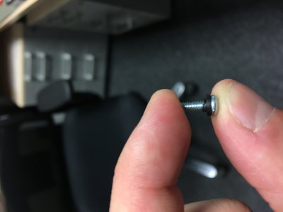
I took off the isolation sheet on the transistor and made sure that I put the vinyl tab on correctly, along with putting the isolation sheet back on.

Here are the voltages for the little board, big board and terminals.
Voltages not in range are listed in red.

Any help or advice is appreciated, thank you!

TerminalsBig BoardLitte Board
1: 75.4VOA: 55VOA: 75.4V
2: 90.6VOB: 76.6VIA: 90.8
3: 0VG: 0VB-A/B: 0V
4: 90.6VB+: 92.5VIB: 90.8V
5: 54.8VOB: 55V
6: 0V
7: 76.3V
8: 0V
9: 53.5V
10: 0V
 
Can you pull the 6080 and remeasure the small board?

It is incredibly likely that you do not have the TIP50 transistors properly isolated from the heatsinks.  It's not just the insulating sheet that goes between the heatsink and TIP50, but also the shoulder washer that sits in the hole on the TIP50 metal tab and insulates the screw from the metal tab.
 
I pulled the 6080 out and measured the little board. the Voltages for the board are as follows.
I am in Germany, so I have 230V mains. Ive also included a picture of the vinyl washer included with the kit.
It seems that part of it is not symmetric where it gets inserted into the transistor top. I have made sure I inserted it correctly, but Ill try it again and see what happens

OA:74.5V
IA:240V
B-A/B:0V
IB:240V
OB:76.5V


Attachments

  • IMG_4638.JPG
    IMG_4638.JPG
    1.4 MB · Views: 45
If it's not properly inserted into the TIP50 it will deform like that and you'll have the issues you're having.  I would recommend replacing it (and the other if it's deformed).

 
Caucasian Blackplate said:
If it's not properly inserted into the TIP50 it will deform like that and you'll have the issues you're having.  I would recommend replacing it (and the other if it's deformed).

I am going to mark this as resolved. When i re-seated the washer, and angled the screw slightly more towards the side where the washer is not deformed, then the amp worked.
I've been using the amp now for a few hours now, and so far no problems. I;m going to order some new washers and replace the deformed one.

Thanks very much for your help, I appreciate it! The help and friendless here is amazingly good.
 
"The help and friendless here is amazingly good."

That's true for sure.  It's great.

Also, thanks for finding this issue and it's something that I will watch for when I get the courage to add the S.B.  I like my amp so much as it is that I'm not very motivated yet.
 
Okay, so I guess I closed the topic too early.
I'm still waiting for my new washers, but I replaced the metal screw and washers with a nylon screw and nylon nut.
After a few hours of use the same problem started happening again :/ So I am back to square one.

@fromnowon I think most of the people who bought the speed ball don't have a problem, and thus don't post about it.
I'm probably doing something wrong here, but I can't just figure it out. My next thought is that maybe the insulator tab (the clear plastic piece)
is deteriorating or faulty some how. However I'm no way certain.

Any other suggestions?

Thanks again for your help
 
If the transistor isn't mounted properly, you'll get a resistance reading from the TIP50 metal tab to ground.  Almost always this is a condition that happens immediately, not after a long time of running.
 
I just ordered some new transistors and insulating tabs. Once they arrive, I'll completely replace the TIP50 for the left channel.
In the mean time, I'll double check all my other solder joints.
 
If the amp is run long enough with this defect, potential damage can occur to the 6080 and/or the power transformer.  It seems like your power transformer is still happy, but do consider that the 6080 might not be.
 
I've replaced the TIP50 transistor at at OA, along with putting in a new nylon washer and new insulator tab on Tuesday, and have been running it daily since.
It has about maybe 20 hours of usage since the replacement, and everything seems to be working fine now.

I guess I can make this as resolved again. It's too bad I couldn't isolate the exact cause of this problem, but I'm guessing it was isolated to this area.

Due to the high temperatures caused by the transistors, my 270 ohm 5 watt resistors by the transformers looks pretty beat.  Well, just the leads and not the resistors themselves.
I'd like to replace them anyway. However, I'm having trouble finding the exact kind and shape that is located in europe. Mouser seems to ship from the USA, which has a high shipping cost.

I did find a 270 ohm 5w resistor (10% tolerance) of a slightly smaller dimension, and I was wondering if this would still work?

Data sheet is here: http://www.produktinfo.conrad.com/datenblaetter/425000-449999/428052-da-01-en-HOCHLASTDRAHTWIDERSTAND_5W_270_OHM.pdf
And I uploaded a picture of it to show the difference

Thanks for your help again, really appreciate it
 

Attachments

  • r1.jpg
    r1.jpg
    1.5 MB · Views: 31
  • r2.jpg
    r2.jpg
    996.8 KB · Views: 24
If they fit, that's great!  The tolerance is exceptionally unimportant there, provided the value doesn't creep up enough to increase dissipation.

The big challenge with the 270 ohm resistors in the Crack is that the one positioned between the two terminal strips needs to have sufficiently long leads to reach between the terminal strips, which your part does just fine.

The negative side of the parts that you've chosen is that the slightly longer body may not fit in the second position against the terminal strip.  For that position, I would let the lead be a little longer on the tube socket side of the resistor.
 
Thanks for the info Paul,
Well I guess I spoke again too soon! Last night the crack started acting up again.

This time the left channel doesn't die out, but rather every few minutes it makes kind of a white noise sound, or a noise like the wind is blowing (music is also playing).
It gets slightly louder, then it makes a pop sound in the left channel then continues working normally. Then a few minutes later the same situation repeats itself.
Increasing or decreasing the volume has no effect on the noise or pop, so I'm guessing the problem is after the potentiometer (and still probably related to the transistor).

I'm going to replace the 2N222A transistor while i replace the resistors, and maybe I'll reflow some components on the big board. If this doesn't work, Im going to put back
the 3k ohm resistors inside to see if maybe some other part is failing. I have 3 sets of output tubes, the standard 6080 (made sparks when I get it, so I don't use it), a second new old stoke 6080, and a 6H13C tube.
All exhibit the same problem.

I thought there maybe a cold joint somewhere, but poking and prodding all terminals produced no pops or audible changes
 
So after a few weeks of no problems, the original problem started showing up again.
Left channel makes huge loud noise scratching noises. The LED closest to the TIP50 stops glowing.

I'm pretty at a loss as what is wrong. I'm not sure how possible it is to mess up soldering one piece so many times haha.
Although my big board visually has no signs of damage, I'm worried that further rework will eventually destroy the big board.
I'm going to take out the big board complete today and reinstall the two ceramic resistors, and then I will post some pictures of the big board from all angles. Maybe you can see something there that I can not. I just find it strange that the crack works for a few weeks at a time and dies.

There's one positive thing though. I'm definitely learning more about electronics along the way. Constant googling, trying to understand how all the components work. It's fun! Although sometimes frustrating :)
 
I have reverted to the stock crack, but left the small board inside. The voltages in the crack manual are all within their ranges including tolerances.
I'll play with the crack for another week or two to see if something strange happens.

I have now uploaded some pictures of the big board. Maybe there is something wrong there that I am not seeing?
 

Attachments

  • IMG_4668.JPG
    IMG_4668.JPG
    1.6 MB · Views: 11
  • IMG_4666.JPG
    IMG_4666.JPG
    2.2 MB · Views: 9
  • IMG_4667.JPG
    IMG_4667.JPG
    1.6 MB · Views: 8
  • IMG_4665.JPG
    IMG_4665.JPG
    2.3 MB · Views: 3
  • IMG_4664.JPG
    IMG_4664.JPG
    2.1 MB · Views: 19
  • IMG_4663.JPG
    IMG_4663.JPG
    1.6 MB · Views: 11
  • IMG_4662.JPG
    IMG_4662.JPG
    1.4 MB · Views: 7
  • IMG_4661.JPG
    IMG_4661.JPG
    1.9 MB · Views: 7
  • IMG_4660.JPG
    IMG_4660.JPG
    1.8 MB · Views: 16
  • IMG_4659.JPG
    IMG_4659.JPG
    1.6 MB · Views: 20
I looked at my working Speedball in my crack and here is what mine looks like:

Its very different looking to mine??

Wondering if this is a later or newer version??

Alex


Attachments

  • Capture.JPG
    Capture.JPG
    43.3 KB · Views: 36
We did do a minor revision to design out those jumpers and replace the front PC board.

Is the hardware nice and tight between your TIP50 transistors and the heatsinks? 
 
Yea the TIP50 is screwed nice and tight against the heatsink. Any tighter, I think I would start stripping the screw and or the nut.
 
By the way, I can't help noticing that the soldering on your boards looks beautiful!

I wonder what kind of solder you used . . .

I'm sure that you will get this sorted out!
 
Thanks for the compliment, but my soldering skills are still quiet amateur haha.
I use a standard 60/40 rosin core solder.
I bought this one on ebay: https://www.ebay.de/itm/321315268878

I work as a software engineer at an automotive firm, and we have a hardware department, so I have good access to a ERSA RDS80 soldering station with all sorts of iron tips. It makes soldering easy from tiny SMDs to point to point. My boss encourages everyone to use the work stuff after hours for their own personal projects.
 
Back
Top