TheCoolDoc
New member
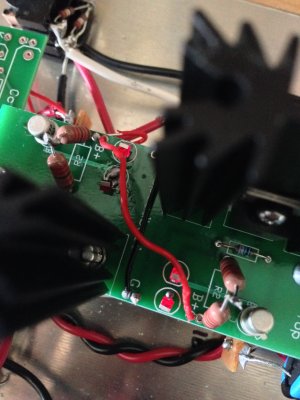
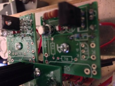
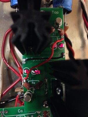
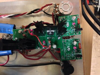
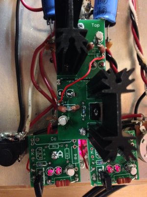
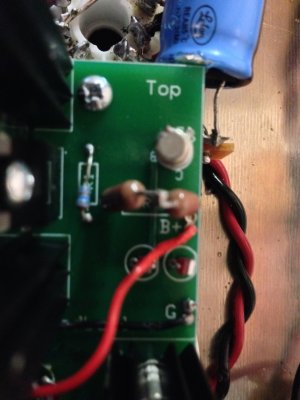
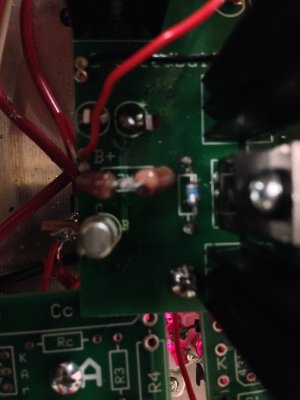
Caucasian Blackplate said:I would suspect that the center leg of each MJE-350 isn't adequately soldered.
It's tough to debug a situation like this, as you had your Crack operational for about a day before installing the Speedball, so there could be some underlying issue that has nothing to do with the Speedball itself.
-PB
The crack has been operational for about 6 days now. It hasn't caused any problems during that time and the resistance/voltage readings were flawless for it. I really think the upgrade has the issue.
I'll try resoldering the MJE-350s.
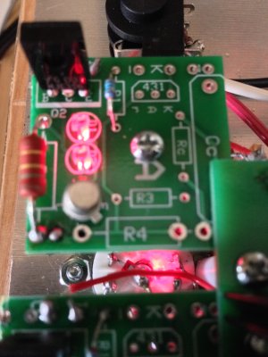
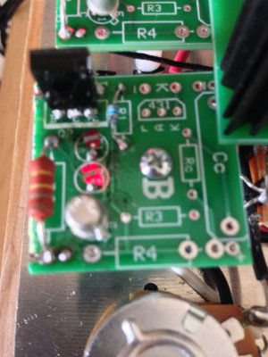
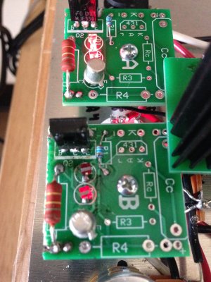
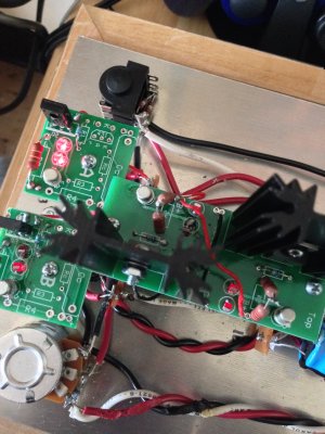
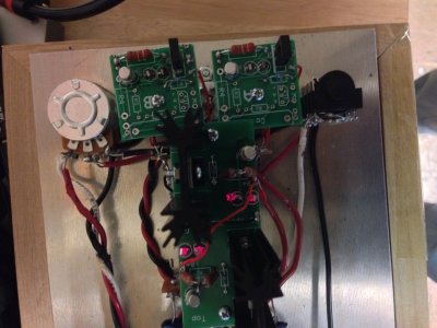
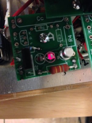
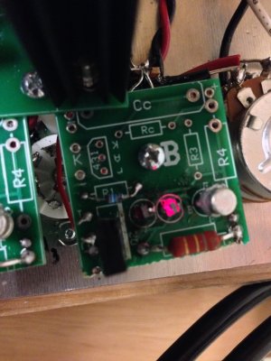
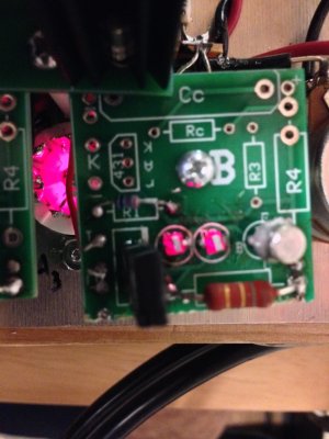
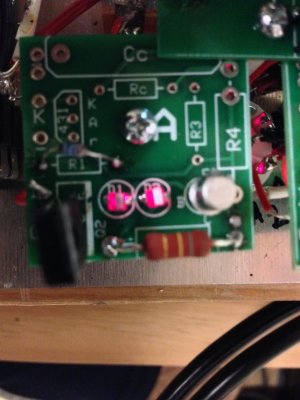
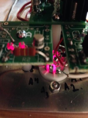
Why would one LED be brighter and one on the B board not work at all?
Is there anything else I can try if it doesn't work? I'll post better pictures so that maybe a second set of eyes can tell.