Rectifier Diode Bad?

Tmielke

New member
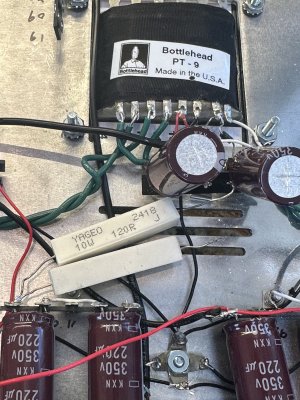
The two UF4007 Rectifier diodes connected to the power supply show a voltage drop of .45 when tested. Google AI says this should be .5-.7. I a wondering if these need to be replaced.

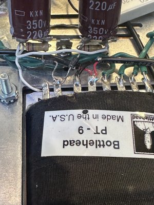
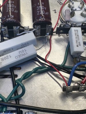
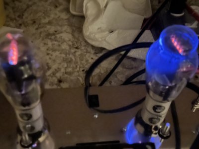
When the 120 ohm resistor is connected to L9, the fuse blows at power up. When it is disconnected the fuse does not blow. At this point all four tubes pass the glow test and there is 190v across pin 7 and 8 of the power supply. Both 270K Ohm resistors test good. Both 220 uF capacitors test ok. One is 214UF the other is 210uF. The 120 ohm 10W resistor tests fine as well. I tested all components removed from the circuit.

The fuse will blow if I check voltage at the L9 end of the disconnected 120 ohm resistor.

This issue is subsequent to a driver board failure due to shorting out a connection when testing voltage.

I hope this makes sense. This is my second kit build. The first being a Moreplay that worked fine.
 
Can you post some photos of the build?

If you had a driver board failure, disconnect the red wire going into IA on that board and retest the amplifier with that board disconnected.

UF4007 diodes will do ~20A or so of peak current, so they are pretty hard to kill. I wouldn't be super concerned about the voltage drop you're seeing, as that may just indicate that the test current your meter is using is very low.
Thanks for the reply.

Both driver boards have been removed as I have been trying to isolate the problem. The 120 ohm resistor that connects the first pair of capacitors by the power supply has been disconnected. There is no power to the red wires that connect to IA.
 
I'd want to see some build photos to have a look.

If the first 120 ohm power supply resistor being disconnected prevents the fuse from blowing, then you have something downstream from there causing excessive current draw, which would not be the UF-4007 diodes.

Does the fuse blow with no tubes plugged into the Kaiju and that resistor connected?
 
All four tubes pass the glow test.

The fuse will blow when I try to check
Voltage at the disconnected end of the resistor. I’ll get pictures later today.
 
I'd want to see some build photos to have a look.

If the first 120 ohm power supply resistor being disconnected prevents the fuse from blowing, then you have something downstream from there causing excessive current draw, which would not be the UF-4007 diodes.

Does the fuse blow with no tubes plugged into the Kaiju and that resistor connected?
Does the fuse blow with no tubes plugged into the Kaiju and that resistor connected? Yes
 
I'd want to see some build photos to have a look.

If the first 120 ohm power supply resistor being disconnected prevents the fuse from blowing, then you have something downstream from there causing excessive current draw, which would not be the UF-4007 diodes.

Does the fuse blow with no tubes plugged into the Kaiju and that resistor connected?
With the 120 ohm resistor disconnected from lug 14 Fuse blows at power up.

This is confusing for me as about an hour ago I was able to get 283V at 9 and 540V at 14 using a jumper. When I soldered everything together including the wire from 15 to 17 I started blowing fuses again. Reversed things again to what you see in the pictures and am blowing fuses at power up.
 

Attachments

  • IMG_2572.jpeg
    IMG_2572.jpeg
    1.8 MB · Views: 13
  • IMG_2573.jpeg
    IMG_2573.jpeg
    1.6 MB · Views: 10
  • IMG_2574.jpeg
    IMG_2574.jpeg
    1.5 MB · Views: 13
How about the wiring at the back of the power transformer and the IEC inlet/power switch?

A fault before the power transformer can also pop the fuse.
 
I’ll double check all that this evening. The fuse does not blow with the diodes disconnected. Voltages at the heater wires is about 6.6V. AC across 7 and 8 is 190V

The ground wires at the lug by the IEC were not soldered. I have soldered them but need to get some more fuses. Would 2 amp be ok?
 
2A would be reasonable.

You can certainly replace the UF-4007 diodes if you'd like. You'll want to put each node of the power supply back onto the power transformer one at a time to know that none of those are the issue, and taking care to not have the 300Bs in the socket while doing this just to remove another variable.

If a UF4007 is causing this problem, I would expect it to read like a piece of wire in both directions with your meter.
Nothing wrong with UF4007. Soldered 2A and no more blown fuse. 10U 269V, 14U 533V, 15U 248V

My guess is it would occasionally not blow the fuse when the alligator clip on 2A secured the connection. Thanks for getting me to look in the right direction.
 
Got the power supply to work
10. 269V
14. 533V
15. 248V

Moves on to voltage check with tubes installed. Had a bit of a problem with the fuse blowing with the D side tube installed.

I was able to get it powered up with both tubes installed.

53. 71.4V
65. 76.1V


The D side tube ran very hot with a bluish glow. The photo over emphasizes the color considerably. Very hot to the touch compared to the A side tube.

Switched tubes to other side and the fuse blew on power up. Switched them back and it powered up but still very hot on the D side
 

Attachments

  • IMG_2576.jpeg
    IMG_2576.jpeg
    2.4 MB · Views: 11
  • image.jpg
    image.jpg
    1.5 MB · Views: 7
  • image.jpg
    image.jpg
    2.3 MB · Views: 7
  • image.jpg
    image.jpg
    2.2 MB · Views: 7
  • image.jpg
    image.jpg
    2.2 MB · Views: 8
Last edited:
Generally blue glow doesn't indicate a problem, as a really hard vacuum will tend to produce more glow. It's good to see both bias voltages around 75V. What are the voltages at pin 1 on each 300B socket?
 
S
Generally blue glow doesn't indicate a problem, as a really hard vacuum will tend to produce more glow. It's good to see both bias voltages around 75V. What are the voltages at pin 1 on each 300B socket?
Got things working with 71V an 71.1V.

No more blown fuses
On to the driver boards.

Thanks
 
Back
Top