Problems after speedball(Solved)

Strikkflypilot

New member
Hi again!

After Caucasian gave me he ok on voltages on stock crack I really enjoyed it and moved on to speedball.
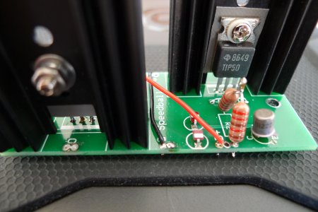
Built everything but now problems.

LED A3 is NOT lighting up. All others do.
Tubes light up.

Terminals:
1. 73,25v
2. 220,5v
3. 0v
4. 220,3v
5. Fluctuating in the -0,something v range!
6. 0v
7. Falling slowly from 200v range
8. 0v
9. Slowly falls from 100v range
10. 0
11. 0
12. 0
13. 220v
14. 0v
15. 225v
20. 0 v
21. 230v


Thoughts? I mean help:)
 
Resolder the center leg of the MJE-350 placed on the PC board that feeds terminal 5.

(Also, don't poke at the LED on A3, it isn't lighting because of other circumstances)
 
Thank You.
I resoldered all the leads of the MJE on the right board.
No change.
Then I did the same with the left board

No change.
 
Can you see both halves of the 12AU7 glowing?

Can you verify that the "I" and "O" wires are leaving the board that feeds T5 properly?

It's very easy to put a 2N2222A in place of a 2N2907, so that's good to check too.
 
Hi and thanks for this.

Both halves of both tubes are glowing.
On the right board, the I is connected to 4u
The O is connected to 5u.
The G is connected to 3u.
The large board has both the 2N2222As connected.
The small boards have the 2N2907As connected
All properly aligned.
I have freshened up the solder on terminals 3u- 5u

Same results.

Additionally the LEDS on the big board are shining bright, like theA8 LED.
The LEDs on the small boards are alle more dim, A3 does not light up at all, at
least not visible to me.
 
You can try swapping the small PC boards left to right, to see if your voltage issue moves to terminal 1.

This still seems like a cold or missing solder joint on that small PC board.
 
Thanks again!

It was indeed board B.
The "B" leg had a layer of rosin around it and what looked like a good joint wasnt conducting.
Used the conductivity test of my meter to pinpoint.

ALL LEDs light up.

1. 64v!
2. 215,3v!
3. 0v
4. 214v!
5. 76v
6. 0v
7. Slowly falling from 200v!
8. 0v
9. Slowly falling from 200v!
10. 0v
11. 0v
12. 0v
13. 216,6v!
14. -(minus) 0v!
15. 221,8v!
20. -(minus) 0v!
21. 227,4v!

What do You think of these? Not quite what I expected.

 
Do 7 and 9 settle somewhere?

They shouldn't really pop up to 200V, that would tend to suggest a miswire on the larger PC board.  (On the B+ pad on that board is at 200V, almost all the rest of the pieces are at no more than +5V, then the collector of each Tip 50C will be at ~100V)
 
Seems to be same problem with the 2N2222As
Also I got a short spark when testing conductivity just touching red probe to center leg of the TIP50 closest to the RCAs
 
Resolderedthe 2N2222As legs.
New startup.

Small boards leds light up A3 lights up A8 flickrrs slightly then lights up.
The two big board leds (where there was a spark from tip50 middle leg) dont light up.

1. Rises quickly to 220v! Then goes down to ca 30 and up again to 67v from where it slowly goes downward
2 slow fall from 100v
3. 0v
4. Slow fall from 100v
5. 75,5v
6. 0v
7. After settling slowly falls from 64v
8. 0 v
9. Slow fall from 78v
10 0 v
11. 0v
12. 0v
13. Slow fall from 100v
14. -0v
15. 143,78v
20. -0v
21. 193v

And I hope the orientation of the large speeboard PCB Isnt crucial. The TOP side points towards pot
 
Can you measure the DC voltages with the "rising" or "falling", put the probe on and report the reading after it stabilizes. 

-PB
 
I still don't have a feeling for what's going on in your amplifier.

Can you post the voltages that you end up with? (Not the behavior, just what they settle to)
 
Thanks for Your help PB.
Will get back to this build when time permits.

If only I had measured continuity for every solder, don't like the idea of having sent Voltage thru an incomplete curcuit.
 
I decided to remove the speedball upgrade and revert to stock, all Voltages are good,
SQ is just as excellent as before.
Going to resolder all points of the boards and be back with a report.

I am considering the fact that possibly very high Voltages flew through the speedball parts,
However if they conduct well and voltages are good, all is well, don't You think?

Edit: Any other way of testing the Speedball boards before soldering them into the Crack curcuit?

By the way, this pic is for JamieMcC:)
 

Attachments

  • image.jpg
    image.jpg
    1.7 MB · Views: 132
Hi.

I guess You didn't see my edit of the last post or it is Sunday.
I now went ahead and checked all solders on the PCBs. They seem solid.

Being no expert I cannot check the transistors properly but the NPNs have high resistance to the emitters and collectors although not identical and the PNPs have high measurable resistances.

I did find a diode that has no voltage drop, maybe related to the spark from the collector of the adjacent TIP50 during my conduction test after voltage tests(after unplugging of course)

I also noticed that the diodes have different voltage drops. Some around 0,75v that don't light up and some at around 1,5v that light up.

Anyway.
The final culprit seems to me to be just one small diode.
 
Your meter's ability measure to the LED voltage drop while they are installed on the PC board is not an indicator of how they function.  For most meters I own, only one of the LED's can be measured.  A few meters will not be able to measure either, and some will be able to measure both.

If the LED isn't in backwards and hasn't visibly exploded, then you can assume that it's working.
 
Thanks for the reply

It just fitted the picture, being one of the two LEDS that didn't light up.
Putting the PCBs back into the curcuit like they are now would only put me back with funky numbers as I haven't changed anything...

Nothing else I could do to troubleshoot before reinstall?
 
I'd post a photo of the top and bottom of the big PC board, we may be able to spot something that you haven't spotted yet.
 
Appreciate Your help.

Here are the pics. You will notice that the emitter leg of one of the 2N2s hardly has solder, but it is on the end where the LEDs did light up and and conduction test is good from that leg to the leg of the small resistor it is connected to on the PCB. That or anything else strike You as rotten?
 

Attachments

  • L1090598.JPG
    L1090598.JPG
    3.5 MB · Views: 154
  • L1090599.JPG
    L1090599.JPG
    3.3 MB · Views: 146
  • L1090600.JPG
    L1090600.JPG
    3.4 MB · Views: 127
  • L1090601.JPG
    L1090601.JPG
    3.6 MB · Views: 119
  • L1090602.JPG
    L1090602.JPG
    3.7 MB · Views: 121
Back
Top