It confirms that it's RFI and that your hand is screening it a little. That is why it was suggested that moving things around a little might make a difference. The RFI can have nodes and antinodes in a room, where it is stronger or weaker. You could also try attaching all three chassis together with wire, i.e., run a wire from Seduction to Foreplay like you have already, and run another wire from ST70 to Foreplay, attached to the same point on the Foreplay chassis as the wire from the Seduction is attached.
You are using an out of date browser. It may not display this or other websites correctly.
You should upgrade or use an alternative browser.
You should upgrade or use an alternative browser.
Problem Seduction pre-amp_radio station in background
- Thread starter choff
- Start date
Paul Joppa
Moderator
I'm re-iterating this because I've not seen any indication it's been checked. By tying the chassis to the signal ground, you allow the chassis plate to act more efficiently as a ground plane shield.Caucasian Blackplate said:...
The ground connection that you added should have been in the preamp, but IIRC the original Foreplay preamps didn't have signal ground tied to chassis. I believe the recommendation was to jumper terminal 13 to terminal 14 to make this connection (which is now standard on all of our preamps).
Paul Joppa said:I'm re-iterating this because I've not seen any indication it's been checked. By tying the chassis to the signal ground, you allow the chassis plate to act more efficiently as a ground plane shield.
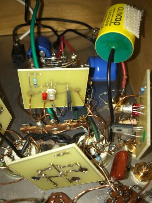
Thank you for the reminder. I'm pretty sure I did make that jumper connection. Can you tell from these photos?
Attachments

Doc B. said:Can we see a pic of the underside of the Seduction?
I want to see more pics of that record collection!
Man, the magnet wire is difficult to photograph and see well.
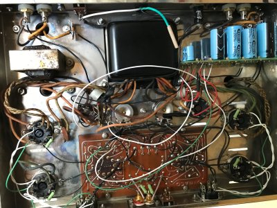
On the five lug strip up front, the middle lug is the chassis connection. There's a light next to it with many wire connections, some of which go to the striped sides of each filter capacitor. Those are the terminals that should be connected (I don't believe they are based on your recent information).
On the five lug strip up front, the middle lug is the chassis connection. There's a light next to it with many wire connections, some of which go to the striped sides of each filter capacitor. Those are the terminals that should be connected (I don't believe they are based on your recent information).
Caucasian Blackplate said:Man, the magnet wire is difficult to photograph and see well.
On the five lug strip up front, the middle lug is the chassis connection. There's a light next to it with many wire connections, some of which go to the striped sides of each filter capacitor. Those are the terminals that should be connected (I don't believe they are based on your recent information).
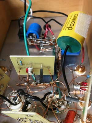
Thanks. I checked again. Perhaps these photos will show it better? 13 and 14 (middle and terminal to left in photo) are definitely connected with a single piece of copper wire.
Attachments
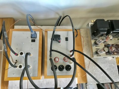
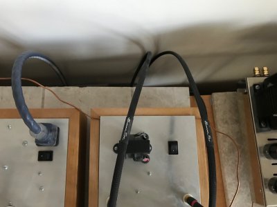
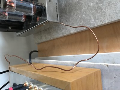
So I hooked some copper wire from some 10-2 romex to the ground on the Seduction, thru the undeside of the Foreplay chassis to hold it tight to the plate because I had nothing to attach to and then to the Dynaco. Not pretty, but this did decrease the radio sound significantly. In fact it almost eliminated it entirely except at the top two settings on the pots with no music playing I could still hear the radio a bit.
Any further thoughts? Suggestions on maybe making this a permanent solution? Thanks so much for everyone's help.
Any further thoughts? Suggestions on maybe making this a permanent solution? Thanks so much for everyone's help.
Attachments
Paul Joppa
Moderator
I know I'm being a dog with a bone here, but the T13-T14 solder joints look a little iffy, and I remember those older Foreplays used a ground wire with really tough insulation that was very hard to solder to. It was a frequent problem on the old Forum. You might try to measure the resistance from chassis plate to T14 (the terminal itself, not the wires soldered to it).
ALL212
Member
For a permanent solution without major mods - use a ground post similar to that on the Eros or Reduction insuring it was grounded at each device. Then run whatever cable you like the looks of from device to device using spade lugs or similar as terminations. That way you can move these around without a solder gun involved.
Paul Joppa said:I know I'm being a dog with a bone here, but the T13-T14 solder joints look a little iffy, and I remember those older Foreplays used a ground wire with really tough insulation that was very hard to solder to. It was a frequent problem on the old Forum. You might try to measure the resistance from chassis plate to T14 (the terminal itself, not the wires soldered to it).
I was finally able to check on this after getting a fresh 9V for my voltimeter. Anyhow, I believe both 13 and 14 check out at 0 ohms. With the negative lead touching the chassis and the positive on the terminals, the voltimeter beeps and shows zero initially and then slowly climbs to around 0.5 on each terminal check. I think the beep indicates that it is zero ohms, as the initial reading indicates?
I should also note that when switching to the Seduction from the cd selection on the Foreplay, there has always been a lot of what I will call "air" at high volume without any music playing compared to the black silent background when set to cd playback. Not sure if this is typical or has something to do with the radio signal I am now receiving?
Really hope I can get this resolved somehow. Thanks for the continued feedback. Much appreciated.
High volume as in higher than you would actually listen? The sound you hear is called tube rush. The amount varies from tube to tube, but in general it only becomes audible at settings higher than one would ever use. That, however, depends a lot on the nominal output of the cartridge you are using. If it is low the signal to noise ratio gets worse. Do you know what the nominal output of your cartridge is?
Cart is a Clearaudio Concept V2 and output is 3.3mV
The air is noticeable at around 10 and becomes very apparent at and above 12 o'clock on the Foreplay volume pots. Most records get played at around 12-2 o'clock on the Foreplay. Some quieter records I have had to go all the way to the last volume setting on the Foreplay. Not really all that noticeable when playing music, but I always wondered why it was so much louder than the dead silent background of the cd player, which is the same at any volume setting.
The air is noticeable at around 10 and becomes very apparent at and above 12 o'clock on the Foreplay volume pots. Most records get played at around 12-2 o'clock on the Foreplay. Some quieter records I have had to go all the way to the last volume setting on the Foreplay. Not really all that noticeable when playing music, but I always wondered why it was so much louder than the dead silent background of the cd player, which is the same at any volume setting.
Just to follow up on this some more and my last post. I spent some more time with the amp trying to see what was and wasn't working with the copper wire, etc.
My conclusion is the wire between all three units helps but not dramatically. What really reduces the radio sound is when I am touching any of the components or wires or have my hand between the Foreplay and the Dynaco.
Also, the "air" I described is really only noticeable on the two or three highest settings on the Foreplay. Just much more obvious now that I hear the local radio station (always the same one) playing classic rock. The station is pretty good, but not what I want to listen to when playing a particular record.
So the bottom line is I don't really think the wire is a solution to my problem. It helps, but I can still hear the radio at normal listening levels starting around 11 o'clock on the Foreplay. Very frustrating. Any further help would be greatly appreciated.
Does your Dynaco have a 3 wire power cord?
Caucasian Blackplate said:Does your Dynaco have a 3 wire power cord?
Yes
That's at the low end of the recommended nominal output for a cartridge into the Seduction with a C4S upgrade. Without the upgrade the gain of the Seduction is 3 or so dB less and the power supply isolation is about 50dB less. Thus the signal to noise ratio will be less optimal than it would be with a more standard 5mV cartridge. This is all with respect to the tube rush.
The RFI problem, if it is is not present in one room and bad in another, is probably going to be tough to tame without spending time checking every ground connection and potential ground loop. Touching the gear and making the noise go away means that you are grounding the equipment better than the existing grounds are. So they need some improvement. There are many ways the interference could be getting into the Seduction - through the cartridge, through the cables, through the power line, etc. So you just have to try a lot of different things to determine of you have a loose ground somewhere. It could be that the mains ground in the outlet you are using is not optimal.
Are the shields of your cables attached to the plug shell at only one end? If the shield is attached at both ends that can create a ground loop.
This is grounding.choff said:What really reduces the radio sound is when I am touching any of the components or wires or have my hand between the Foreplay and the Dynaco.
If the wire between the ground post on the Seduction and the chassis of the Foreplay made any difference at all, then the jumper we have mentioned previously is not well soldered and needs to be reheated. This jumper serves the same purpose.
I would connect one end of your DVM to the ground post of the Seduction, then measure the DC resistance to the Foreplay chassis plate and the DC resistance to a screw on the Dynaco chassis. What do you get?
What is the ground wire on the power cord going to the ST-70 connected to?
I'd also recommend buying one of those inexpensive outlet testers with the three bulbs to check your outlet. This could be a grounding issue at the outlet.
All the questions about the 3-wire power cord jogged my memory that I may never have attached the ground wire back in the day when I made that upgrade.
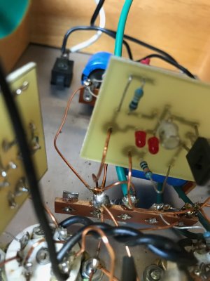
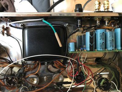
Popped the top and sure enough (see attached photos) the green wire with the beige sleeve is not attached to anything. I believe should be the ground wire? Can't remember why, but whoever I was consulting with on the work at the time said it wasn't necessary. The white wire goes to the power switch and the black wire to the fuse.
Could this be the source of the trouble?
Attachments
Similar threads
- Replies
- 9
- Views
- 2K
- Replies
- 20
- Views
- 11K
- Replies
- 2
- Views
- 3K