Possible Channel Imbalance[Solved]

XforceVesa2

New member
Hello Community,

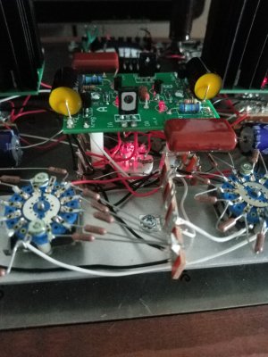
I've Build my Crackatwoa a few weeks ago and everything seems fine , except one thing.

I was the entire time unsure if my Crackatwoa actually has an channel Imbalance or not because I could swear that im Hearing the Left channel a little bit louder than the right channel and thought it was just my imagination.

But today I took measuring from my Headphone Cable (HD 600 the Cable is Detachable) and got the following measurements:

At my "normal" listening Volume I've got:

L = 0,22V

R = 0,21V

So it equals to (if I'm not mistaking) an Channel Imbalance of 0,4 dB.

I've took another measuremnt, this time with the Volume upt to 0dB(I have the TwoQuiet Stepped attenuator) and got these measurements:

L = 12,05V

R = 11,29V

So the channel Imbalance is 0,6 dB.

I hope you can help me with that Problem.


Can you repeat the test but measure Q7 and Q9 instead (the amp can be off) just to ensure that the channel balance is OK coming out of the attenuator?
 
I've measured Q7 and Q9 with the Volume set to max(0dB) and got the Following Measurements:

Q7 = 1,06V

Q9 = 1,08V

Edit: I've used for all my measurements a 60 HZ Test Tone.
 
The attenuator balance looks good. 

A problem like this is usually either a solder joint that isn't 100%, or just a bit of tube imbalance (in the 12AU7).

-PB
 
It's a bit of a roll of the dice unless you pay a tube vendor for one that has been manually checked.  You may also find that the imbalance fades a bit once the tube has been run in for 100 hours. This of course presumes that the tube is the issue and not a flaky solder joint.  If it's a bad joint, then all 12AU7s will appear to have the same imbalance.

How are the OA/OB voltages on your center PC board?
 
I've got at OA = 70,3 V and at OB = 73,2 V


Edit: I don't know if it could have to do with that problem but If I look at my Input tube it seems like that on the bottom part of that tube one side glow a little bit brighter than the other?
 
12AU7 tubes are relatively cheap, even some NOS ones. There are NOS Sylvania made for Baldwin organs 12UA7 tubes on sale for $12.00 right here for example:

http://www.audiotubes.com/12au7.htm

Much further down on the same page they offer GE organ stock tubes for $9.00. Current production 12AU7 tubes cost roughly the same.
 
I can swear that I can hear the Channel Imbalance(Left is a little bit Louder).

Are there any contacts in the Amp that I can measure too to find the "Possible" Problem?

 
When the 12AU7 has amplified the signal, there is DC in the presence of the AC voltage.  You could try measuring the AC voltage at pins 1 and 4 on the octal socket, but your meter may not resolve the AC on top of the DC all that well.
 
I would measure this next Time.

Should I check all Solder joints in the Amp or only these near the Input and Power Tube?

During the Build I've checked almost all Solder Joint with my eyes and my multimeter(checked the connections from one solder joint to another with the Impedance check that its always shows 0.00 Ohms).

In the Input socket both leds are lit bright if the amp is On, only on the Larger PC Board I've noticed that the Leds on it doesn't lit so brightly like the Others Leds did.
 
There is another way you can measure before you do a whole lot of work. This is going to be short, because I'm in a rush.

Do you have a soundcard in a computer? If, yes, then:

find online or create yourself a 1kHz signal at least 30 sec long / loop if shorter
play it back through soundcard and measure with AC rms meter - adjust -  0.77V or 0.5V are both good
install voltage divider in eros input - go for something like -40dBV or a bit more attenuation
play signal from soundcard into one channel of Eros at a time and use the same output on the soundcard for both Eros channels

that way you can be sure that what goes in is the same for both Eros channels

measure AC V rms at the output


Could the Channel Imbalance have something to do with the Large PC Board as stated above?

What Channel Imbalance does the Crackatwoa normally have?

Are these Values that I have measured at the begin at this Thread a imbalance that normally Occur at this Amp?
 
XforceVesa2 said:
Could the Channel Imbalance have something to do with the Large PC Board as stated above?

What Channel Imbalance does the Crackatwoa normally have?

Are these Values that I have measured at the begin at this Thread a imbalance that normally Occur at this Amp?

Paul Birkeland said:
A problem like this is usually either a solder joint that isn't 100%, or just a bit of tube imbalance (in the 12AU7).
As I mentioned before, channel balance is far more tube dependent than circuit dependent.  Creating a spec for channel balance would require a sample of maybe 100 12AU7s to give an average expected channel balance along with the distribution of what was actually measured.  This is one consequence of not having global feedback, if we put feedback around the amp I could make the channel balance less than 1/4 of a dB pretty easily.

XforceVesa2 said:
Could the Channel Imbalance have something to do with the Large PC Board as stated above?
Which board is the large board?  Can you post a photo of what you're seeing?
 
I was and I still am in a rush. Sorry. Plan can be adapted to the Crackatwoa, skip the attenuation, set the volume control to a couple of different points, three or so, alternate channels at each setting.

I suggested buying another one or three reasonably priced 12AU7 tubes because the amplification factor of the Crackatwoa depends on that a lot.
 
Paul Birkeland said:
As I mentioned before, channel balance is far more tube dependent than circuit dependent.  Creating a spec for channel balance would require a sample of maybe 100 12AU7s to give an average expected channel balance along with the distribution of what was actually measured.  This is one consequence of not having global feedback, if we put feedback around the amp I could make the channel balance less than 1/4 of a dB pretty easily.
Which board is the large board?  Can you post a photo of what you're seeing?

Ok I think I now understand what you meant :D

I have again took an Inspection of the Socket from the Input tube and couldn't find a problem.
The solder joints seemed fine, I have measured the impedance from one solder joint to another end e.g hold one probe of the multimeter against one pin and the other probe at the other end of the soldered wire, my reading was 0.00 Ohms, also the two LEDs on the Input socket lit bright when the amp is On.

I've meant the Low Current C4S Board.

I don't have a problem with the slight channel imbalance I was just worried that I've could made a mistake in the circuit and thats what I just wanted to be sure that there's no mistake in my cicruit :D
If the channel Imbalance comes from the Tube then I can live with that.
 
If you have a large difference in LED brightness on the center low current C4S board, that would tend to indicate a possible soldering problem. 
 
I have uploaded 4 Pictures that shows the different leds on the circuit.

I've meant that all the LEDs in the Amp seems to lit equally except the LEDs on the Low Current Board(the four LEDs on this boards are equally less lit than the other LEDs in the Amp).

I hope that the pictures shows it better than what I try to explain what I mean(Its not my native language)  :D


Attachments

  • IMG_20200123_102314.jpg
    IMG_20200123_102314.jpg
    1.5 MB · Views: 12
  • IMG_20200123_102330.jpg
    IMG_20200123_102330.jpg
    1.6 MB · Views: 6
  • IMG_20200123_102352.jpg
    IMG_20200123_102352.jpg
    1.4 MB · Views: 2
  • IMG_20200123_102402.jpg
    IMG_20200123_102402.jpg
    1.5 MB · Views: 8
Back
Top