Paramour 1 with various upgrades - zero voltage on 12AT7 [resolved]

patrickamory

New member
Hello,

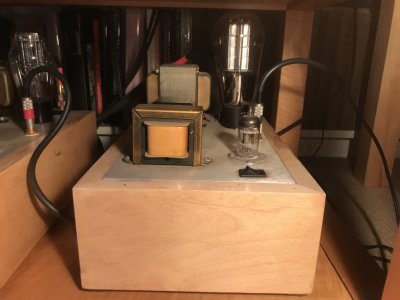
It's been a very long time, but I hope someone can help me with one of my Paramour 1s. They'd been sitting on the shelf for years, but my main amp has to go back to Japan for repairs. I put them in the system since I have new extremely efficient horns. One monoblock works great; the other only emits a low hum. The tubes light up but there is no output.

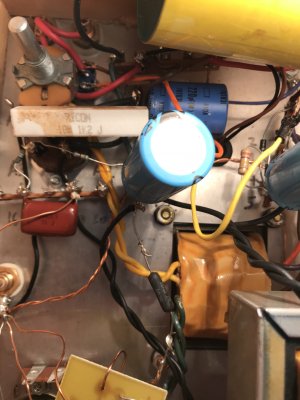
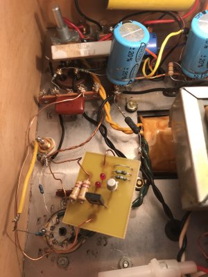
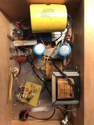
I built the Paramours in the year 2000 and I'm pretty sure made the following changes in the few years following:

- C4S
- Magnequest BCP-15 chokes
- "Big Iron" transformer upgrade
- Modded to accept 76 tubes, then modded back but installed a rocker switch so that I could go back and forth (wrong - the rocker switch actually selects 4 ohm or 8 ohm taps on the OPT) - currently using 12AT7s
- TJ Meshplate 2.5V 300Bs swapped in for the 2A3s
- Various cap upgrades as recommended at the time - can't remember which ones but included the big yellow cylinders :)

Voltages on the no-output amp all check out until I get to the 12AT7, where I have zero volts at B1, B2 etc.

C4S diodes light up as expected.

Any suggestions?

I've attached a photo of the unit.

Thanks!

Patrick
 

Attachments

  • IMG_6732.jpg
    IMG_6732.jpg
    3.6 MB · Views: 45
The C4S kit used only one section of the 12AT7, so the other section (pins 1, 2, and 3) were grounded. So if it is built as in the C4S manual that I have ("copyright 2001") those pins should be at zero volts.

If the C4S LEDS are lit, it and the associated tube section are probably operating correctly.

First thing is to swap the channels to be sure it's the amp and not the interconnects and/or other gear. Then swap the tubes between amps to be sure it's not the tubes. Then check the voltages - especially B6, B7, and B8.

If you pass all those tests, and the 12AT7 voltages are appropriate, then the issue is likely to be a marginal solder connection that has failed while sitting on the shelf.It's fairly simple to merely re-heat each connection, adding a tiny bit of solder if they seem s little dry.

 
Hi Paul,

Great to hear from you, and yes my C4S manual is copyright 2001.

I'm going to proceed with the tests you recommend and will report back.

Thanks!!!

Patrick
 
Hi Paul -

Switched inputs, speaker cables, tubes - the good amp works fine and the problem amp still has no output.

Took it back out of the system. All voltages check out fine, including B6, B7 and B8.

So I'm going to re-heat the connections - are there any in particular to which I should give special attention? Or just re-heat all the connections throughout the amp? Including on the C4S board?

Thanks again,
Patrick
 
I would be interested in seeing the build out on the bottom side of your amp.  What are your B6 and B8 voltages?  How about your voltages on the 4 pin socket?

If all your DC voltages are consistent with what's in the manual, I would suspect that the coupling cap is disconnected or perhaps the wiring from the RCA jack to the 12AT7. 

In the absence of anything I said above being helpful, you can play a 60Hz tone into your running amp at full blast from your phone (go ahead and leave the amp disconnected from your speakers for this one).  With your meter set to AC volts and the black probe grounded, you should see about 300mV of AC voltage at pin 7 on the 12AT7 (could be more or less depending on your phone), about 50x that much AC voltage at pin 3 of the 2A3 socket, then several times more AC voltage on the output side of the parallel feed cap (which may or may not be grounded depending on the amp).

-PB
 
Hello Paul,

Three pictures of the underside attached. The soldering is not pretty - this was my first project, 18 years ago!

Voltages all check out with what's in the manual, but I have to wonder whether near zero volts on A3 (this is not listed in the manual) is a clue?

B6 - 163V
B8 - 1.936V

A1 - 61.88V
A2 - 363.4V
A3 - 0.02V
A4 - 62.02V

Interesting that you mention the coupling cap... at some point I upgraded this to an Auricap as you can see in the photo. It appears to be solidly connected at both terminals though.


Attachments

  • IMG_4161.jpg
    IMG_4161.jpg
    3.6 MB · Views: 33
  • IMG_8065.jpg
    IMG_8065.jpg
    3.8 MB · Views: 33
  • IMG_5813.jpg
    IMG_5813.jpg
    3.8 MB · Views: 41
The Auricap in your photo is the parallel feed cap, which is similar to what we refer to as the coupling cap, but it's on the output stage.  The coupling cap in your amp is the little brown box.

Speaking of, that resistor that connects to A3 and passes over A2 should be bent away from A2.  You don't want it to touch A2!

I'd add a little more solder to B6.  It's possible that the wire going from the C4S board to B6 is well connected, but the one leaving B6 is not.  B8 would probably benefit from a little extra solder as well.

 
Resoldered B6 and B8 and checked voltages - 161V and 1.936V respectively.

Checked continuity on all connections between RCA and 12AT7. Checked the (real) coupling capacitor is firmly soldered and checked continuity on its connections. Resoldered A3 for completeness sake.

Bent away the resistor that comes close to A2!

Hooked up the amp again - same deal. Tubes light up, but no output.
 
Paul: just tested with the 60 Hz tone from my phone. I measure:

B7 = 0.3 VAC
A3 = 3.4 VAC
21 = nothing / open

I'm guessing that that measurement at 21 is the problem?

luddite: sorry for my ignorance, but which pins on the 12AT7 are the heaters?

Thanks again guys
Patrick
 
patrickamory said:
B7 = 0.3 VAC
A3 = 3.4 VAC
I forgot that the cathode resistor is unbypassed on the 12AT7. That will lower the gain a bit so these two numbers look OK to me.
patrickamory said:
21 = nothing / open
It's hard to see into the amp, but is 21 where that big Auricap connects to one wire of the output transformer up top?  No AC voltage there is a bad sign, mostly for the cap itself. 

On your output transformer, there are the two wires that go to the speaker binding posts, then there's the other pair coming out of the other side.  What DC resistance do you get on this pair of wires?
 
I may have measured the wrong location - 25 is where the Auricap connects to the blue wire from the output transformer.

Output transformer wires: there's a pair on one side and 4 on the other. The pair is blue and red. Blue goes to one side of the Auricap as above, red goes to the hum pot via a cap and resistor.

Of the 4 on the other side, one pair (orange and brown) goes to the binding posts, and one pair is split as follows:

black - to the hum pot
yellow - tied off

Should I strip the yellow and measure DC resistance across it and the black?
 
patrickamory said:
I may have measured the wrong location - 25 is where the Auricap connects to the blue wire from the output transformer.
Yeah, see if you can get an AC reading there.  The absence of one might just be your meter struggling to measure AC in the presence of DC.
 
What AC voltage do you see across the speaker posts? 

Your amp gain still seems a little low to me, but these test are still helpful.
 
2.5V at the speaker terminals is just under 1W into 8 ohms.  This is audible.  There is a decent chance that you amp is working fine but you have a cable issue.
 
I was thinking that too, but I switched both the interconnects and the speaker cables (testing each combo separately) to the other Paramour and they work fine. Both speakers are fine (the good Paramour was driving the left and is now driving the right), as are the channels from the preamp.

I thought it might be the jacks in the problem Paramour, but I measure continuity between the center and the outside of the RCA jack and the connections underneath. Same for each speaker binding post.

I'm stumped!
 
It could be something that's moving when you flip the amp over.  I've had this happen before, it can be pretty tedious to figure it out!  (It's also one of the reasons that we now put so many tie down points in our amps)
 
Back
Top