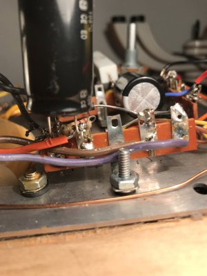
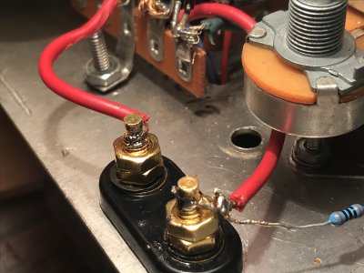
No, I think you have a short between two adjacent terminals. It looks like those two terminals where that capacitor is in your photo are connected together.
You are using an out of date browser. It may not display this or other websites correctly.
You should upgrade or use an alternative browser.
You should upgrade or use an alternative browser.
Paramour 1 - 27 mv hum problem
- Thread starter patrickamory
- Start date
patrickamory
New member
Hi Paul -
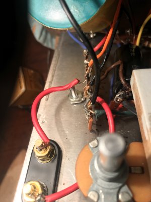
I don't think so? Please see more detailed photos attached.
I read increasing and decreasing megaohms between the two terminals which I'm assuming is the effect of the capacitor.
Please let me know what I'm missing...
Thanks,
Patrick
I don't think so? Please see more detailed photos attached.
I read increasing and decreasing megaohms between the two terminals which I'm assuming is the effect of the capacitor.
Please let me know what I'm missing...
Thanks,
Patrick
Attachments
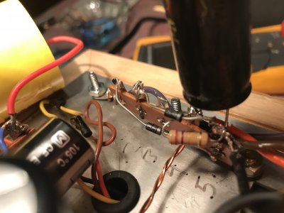
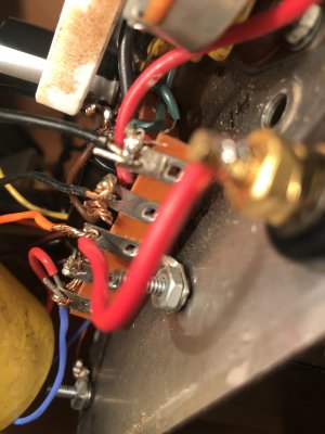
That last angle does show separation.
You can measure the AC voltage between brown and purple to ensure that the power transformer is still delivering the goods.
You can measure the AC voltage between brown and purple to ensure that the power transformer is still delivering the goods.
patrickamory
New member
Hi Paul,
I measure 642VAC across brown and purple. So the PT is alive?
I should have mentioned that both tubes glow, and the C4S diodes light up.
Thanks again,
Patrick
I measure 642VAC across brown and purple. So the PT is alive?
I should have mentioned that both tubes glow, and the C4S diodes light up.
Thanks again,
Patrick
Then your high voltage DC rail is operational.patrickamory said:the C4S diodes light up.
patrickamory
New member
Thanks Paul - I just measured VDC at 5 and 15 now and they are fine.
Hooked up the amp and the hum is almost inaudible (the gain is slightly less too - but only slightly actually the gain is much lower).
So on to the next unit now - hopefully replacing the filter caps has solved the problem! Thank you once again for all the help.
Hooked up the amp and the hum is almost inaudible (
So on to the next unit now - hopefully replacing the filter caps has solved the problem! Thank you once again for all the help.
patrickamory
New member
Now I've done the other amp, voltages all check out correct, but I'm getting a tiny, distorted signal.
I did replace the binding posts - I'm guessing there's a poor connection there if all voltages are on point? Will try reheating tomorrow.
Getting there.
I did replace the binding posts - I'm guessing there's a poor connection there if all voltages are on point? Will try reheating tomorrow.
Getting there.
patrickamory
New member
Second amp is putting out a very low, distorted signal. I read 0.19 VAC on a 60 Hz test tone, input jack shorted. I switched both tubes - same result. Voltages all check out as do resistance readings.
Solder joints for the 3 replaced caps all seem fine.
Any suggestions on what to check next?
(The good news is that the hum is down to 2.6 mV.)
Solder joints for the 3 replaced caps all seem fine.
Any suggestions on what to check next?
(The good news is that the hum is down to 2.6 mV.)
You can play the 60Hz test tone, then measure the AC voltage at the RCA jack, at pin 3 of the 4 pin socket, and at the speaker binding posts, then report those readings here.
patrickamory
New member
Hi Paul,
Here are the readings at those points with the 60 Hertz test tone, plus T25 (where the positive end of the parafeed cap connects to the blue wire from the OPT):
- RCA jack: 0.03 VAC
- A3: 11-13 VAC
- Binding posts: 0.08-0.10 VAC
- T25: 17 VAC
Thanks again,
Patrick
Here are the readings at those points with the 60 Hertz test tone, plus T25 (where the positive end of the parafeed cap connects to the blue wire from the OPT):
- RCA jack: 0.03 VAC
- A3: 11-13 VAC
- Binding posts: 0.08-0.10 VAC
- T25: 17 VAC
Thanks again,
Patrick
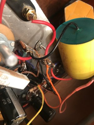
There is something connected on the primary of the OT or on the output of the OT (including the binding posts) that shouldn't be there or that is touching both terminals. The signal is sitting there appropriately on the input side of the transformer but isn't making it out. There should be a little less than 1V of signal at the binding posts under your testing conditions.
patrickamory
New member
Hi Paul,
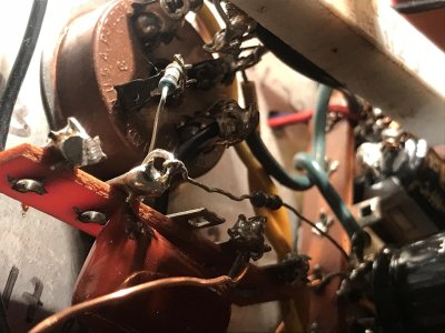
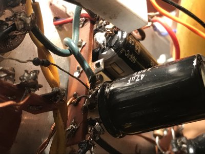
I'm stumped. I can't see any short circuits or connections in the area. Is it possible there's something wrong with the OPT?
I've attached some pictures.
Thanks,
Patrick
I'm stumped. I can't see any short circuits or connections in the area. Is it possible there's something wrong with the OPT?
I've attached some pictures.
Thanks,
Patrick
Attachments
patrickamory
New member
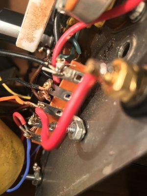
2wo said:Sorry to say but a lot of the solder joints don't look good at all, especially the strip adjacent to the outputs. If it were me I would cut/unsolder all of them and start over...John
No worries about criticizing the joints - I made this amp 17 years ago and it was my first project... they are really ugly, I agree.
I'll give that a try and see if it solves the problem. Thanks!
patrickamory
New member
Well, I reheated and cleaned up the solder joints on the terminal strip by the outputs.
Reconnected the amp, and now it doesn't power up at all! Which is odd because I didn't touch the PS.
Checked the fuse - intact.
Power cord wiring - intact.
Power supply wiring and joints - look fine.
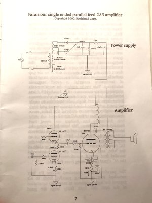
Checked resistances - all check out except for T25 which should be 200 ohms but is coming up at 1200 ohms - I don't know if this is significant? T25 is where the positive side of the parafeed cap connects with the blue lead on the OPT, which the documentation says connects the primary to the plate.
Checked voltages - 120 VAC from the power cord, 0 VAC at T1 and T2, other side of the PT.
Any further advice?
Reconnected the amp, and now it doesn't power up at all! Which is odd because I didn't touch the PS.
Checked the fuse - intact.
Power cord wiring - intact.
Power supply wiring and joints - look fine.
Checked resistances - all check out except for T25 which should be 200 ohms but is coming up at 1200 ohms - I don't know if this is significant? T25 is where the positive side of the parafeed cap connects with the blue lead on the OPT, which the documentation says connects the primary to the plate.
Checked voltages - 120 VAC from the power cord, 0 VAC at T1 and T2, other side of the PT.
Any further advice?
Based on your descriptions during this thread, every time you are going in to do work on the amp, the problems it has change. This does indicate lots and lots of flaky solder joints. Starting over isn't a bad idea, and if you sent it to me for legacy kit repair work, that is likely what I would do.
-PB
-PB
galyons
Member
Paul Birkeland said:Based on your descriptions during this thread, every time you are going in to do work on the amp, the problems it has change. This does indicate lots and lots of flaky solder joints. Starting over isn't a bad idea, and if you sent it to me for legacy kit repair work, that is likely what I would do.
-PB
I think the PB's advice is spot on! It is a simple build with relatively few solder joints. Disassemble, lose the stranded wire and re-solder all of the connections with good solid core wire. You will likely spend more time chasing problems around the unit than a rebuild would take.
Cheers,
Geary
patrickamory
New member
Thanks guys! I'm going to do it.
patrickamory
New member
I have not replaced the wiring but I have resoldered every component and am still seeing the same problem and getting the same voltage readings.
Before I send this off to Paul (if he'll accept it), I wonder whether there's an obvious problem that anyone can see from the input voltages - possibly a problem with the power transformer? The PS voltages are at 60-80% of what they should be. The C4S diodes don't light up (I thought one was bad but it's fine), and zero voltage reaches the 2A3.
I've even disassembled the power cord and checked that 120 VAC is coming through from the wall.
HV secondaries: 262 VAC on each (315)
First filter cap: 250 VDC (395)
Second filter cap: 176 VDC (390)
2A3 filament: 0 VDC (60)
2A3 plate: 0 VDC (365)
C4S input: 122 VDC (295)
12AT7 second section plate: 120 VDC (155)
12AT7 second section cathode: 1.3 VDC (2)
The figures in parentheses are the proper voltages according to the manual & C4S manual.
All resistances check out.
Both tubes glow.
It seems to me that insufficient power is making its way through the PS to the C4S, which in turn means the 12AT7 is not driving the 2A3.
I have checked and resoldered EVERY connection throughout the PS, paying special attention to the PT leads.
Sorry - I promise this is the last post I'll make about this amp if the answer is still bad soldering joints - but I thought that maybe the consistency of the voltage readings might be a clue.
[Edit: attached original schematic, pre-C4S.]
Attachments
You are on the verge of destroying this amplifier. That is 275mA of DC current being drawn from a transformer designed to provide 75. You will blow these up if you keep running them.patrickamory said:First filter cap: 250 VDC (395)
Second filter cap: 176 VDC (390)
If the 2A3 plate is 0V, then this is extremely concerning. Perhaps the 2A3 isn't inserted in the socket properly?
Something is drawing way more current than it should. The power transformer voltages seem low because you're slamming it with several times what it's supposed to provide.
You are welcome to send these to me, but I will strip everything out any only reuse the transformers.
Similar threads
- Replies
- 1
- Views
- 3K