Paramour 1 - 27 mv hum problem

patrickamory

New member
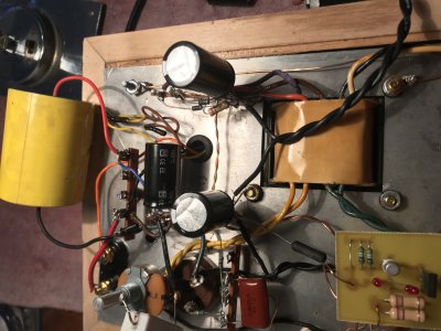
So I continue to enjoy my revived Paramour 1s, but the hum is significant through my horns. Implementing PJ's recommended C4S ground connection from B9 to T14 did not have any effect on it.

Ancient components and clumsy soldering: I decided to reflow all the joints on one unit to see if that helped.

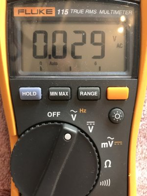
After doing that, the lowest I could get the hum was 27 mv, which is about 10X what it should be. This is with a shorting plug in the input jack, the amp warmed up for 15 minutes, and measuring VAC across the speaker terminals.

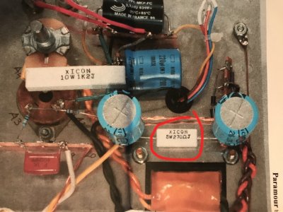
What should I attack next? I have located replacement filter caps, cathode bypass caps, grid blocking resistors, coupling caps, parafeed caps, binding posts, etc. in my workbench or online. Are any or all of these likely to be the culprits?

I also have extra ceramic 9-pin tube sockets. I don't have any extra bakelite 4-pin sockets, and in fact a small piece of one of those cracked when I inserted the new Sophia Electric 2.5V 300B in it a couple weeks ago.

Or... is it likely to a problem with PTs?

Thanks for any advice you guys can provide. Still loving the sound of these, just would like to get that noise down.
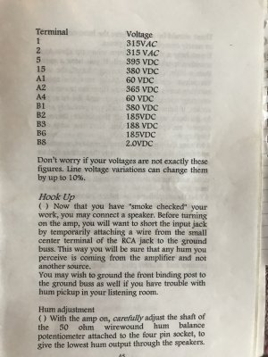
 
Out of curiosity, where are you located? 

Do your power transformers say "PT-2" or "Hammond" on them?

Can you post some photos of your build?

Is your noise 60Hz or 120Hz (listen to these tones online, then let us know which noise sounds more like what's coming out of your amp).

I would very strongly suggest not just replacing random parts.  There's something else at work here that needs to be diagnosed and debugged first.

-PB
 
Located in New York City (Manhattan).

Power transformers have the Hammond "H" on the side sticker and say Made In Canada. I'm pretty sure my kits were among the first round of Paramours and that this is the original PT.

Photos at these links - these are the same that you helped me with in the thread "Paramour 1 with various upgrades" two below this one - except that I have fixed a couple of the issues that you noted, as discussed there:

https://bottlehead.com/smf/index.php?action=dlattach;topic=11132.0;attach=16577
https://bottlehead.com/smf/index.php?action=dlattach;topic=11132.0;attach=16579;image
https://bottlehead.com/smf/index.php?action=dlattach;topic=11132.0;attach=16581;image
https://bottlehead.com/smf/index.php?action=dlattach;topic=11132.0;attach=16583;image

I think the noise is 120 Hz, having compared the sound to a couple of YouTube videos.

Thanks,
Patrick
 
If the DC voltages are correct and you have 120Hz noise, I would be looking at how well connected your power supply caps are.

I see some "extra" ceramic caps in your amps, they are not anything we ever prescribed.
 
Ah those ceramic caps... I have a vague recollection of a VoltSecond or Quest noise reduction mod for the C4S Paramour. Some kind of snubber, and ceramics were recommended.

Should I remove them?

Is it worth replacing the 220uf 47uf electrolytics at the same time?
 
Yes,  I would remove the caps, especially since you have the C7X in the power supply.

What is the voltage rating of those 220uF caps?  I believe 47uF/450V parts were supplied originally. 
 
The caps are old enough that it won't hurt to replace them. 

I would recommend the Panasonic ED radial caps with leads.  These are a lot easier to install than the old snap-in caps.
 
Removed the ceramics in one unit. Voltages all check out.

But the hum is still 29 mVAC if I'm reading the meter right - please see attached photo. I hear the buzzing now as a little softer and more trebly when hooked up to the speaker, compared to the unit that still has the mod in it.

Next step: order the Panasonics and replace the 47ufs?


Attachments

  • IMG_4087.jpg
    IMG_4087.jpg
    3.7 MB · Views: 9
On your meter, there is the "mV" setting that will more accurately display the reading, but I'm sure it will be about the same. 

The hum pots are working properly also, yes? (Just to tackle the obvious)

I'd go ahead and replace the power supply caps.  I'd also recommend ordering a pair of 220uF/250V  Panasonic ED radials to replace the cathode bypass caps while you're in there.

These efforts may not resolve the buzz, but it will remove something from the list of possibilities.

-PB
 
Yes the hum pot seems to be working - the figure varies from about 40 down to about 27 mV.

I'll replace the PS and cathode bypass caps and report back after.

Thanks again,
Patrick
 
One thought, when you adjust the hum pot, is the lowest reading you get somewhere in the range of adjustment. Meaning not at one stop or the other...John 
 
2wo said:
One thought, when you adjust the hum pot, is the lowest reading you get somewhere in the range of adjustment. Meaning not at one stop or the other...John

Hi John yes... more or less in the middle I think. Patrick
 
I'm now in the process of replacing the PS capacitors, and I suddenly noticed from the original Paramour instructions and diagram that I don't have the 270 ohm WW resistor connecting terminals 5 and 15 - in either amp.

I'm not sure how I lost this, but could its absence be the source of my extremely high hum level?
 

Attachments

  • paramour_instructional_photo_with_ww_270.jpg
    paramour_instructional_photo_with_ww_270.jpg
    4.3 MB · Views: 19
  • IMG_8080.JPG
    IMG_8080.JPG
    1.7 MB · Views: 20
Oh right - I completely spaced on that  :)

So I have installed the new caps and am reading -2VDC at terminal 5 and 15. Resistance check shows open at terminals 1, 2 and 4.

Did I fry the diodes?
 
You'll have to be a bit more generic with your voltage values; I have no idea where my Paramour 1 manual is at the moment and I don't have an electronic copy.

If you have -2V coming out of the positive side of your rectifiers, then there's a problem (blown fuse?).  As always, posting photos can be helpful.

-PB
 
Hi Paul -

Sorry for the vagueness.

The fuse is intact.

Attached are photos of the voltage readings page of the manual, and a photo of terminal strip 1-5. I did move one of the diodes from the top to the bottom hole of terminal 5 because it was getting a bit crowded on top.

Thanks,
Patrick
 

Attachments

  • IMG_1302.jpg
    IMG_1302.jpg
    3.8 MB · Views: 18
  • IMG_7999.jpg
    IMG_7999.jpg
    4.6 MB · Views: 31
If a diode body shorts the two terminals where the capacitor connects, you will get no voltage out of the rectifier bridge or full wave rectifier and you will damage your power transformer (though the fuse should pop first).
 
Back
Top