This is something that I try to convey with only moderate success. On average it is faster to reheat all the solder joints in an area of the amp where you are having a problem than by poking around and then reheating what you think might be the problem spot.
You are using an out of date browser. It may not display this or other websites correctly.
You should upgrade or use an alternative browser.
You should upgrade or use an alternative browser.
Paramount voltage concerns **SOLVED!!**
- Thread starter wullymc
- Start date
Thanks guys for the help.
Tomorrow (I hope) I will take off the pcb and resolder/flow all the points. At that point I will also take some pictures with my camera and upload them here. Hopefully this will solve all the issues with this one. When I was listening for the 30 minutes when both were working I was amazed at the resolution. Really exciting. Just can't wait to get this one going again.
If all else fails I will send this one to you for assistance.
Take care. Thanks again for the support, encouragement, and patience! I really appreciate it.....Dave
Paul Joppa
Moderator
Patience is the key - diagnosis and treatment is sometimes painfully slow by forum posts, but we nearly always get there! Once you do get it stable, wait for the break-in; it will take 20-50 hours of music before the capacitors and transformers are sounding right.
Thanks Paul.
I couldn't wait until tomorrow. Kids are asleep!
I took off the pcb and resoldered all connections. Soldered the pcb to the correct locations..on the B terminals and 16 & 17.
Did my resistance checks:
reading Manual
-----------------------------------
1 infinity *
5 999 1K
6 1115 1118
7 247K 249K
9 infinity 124K *
10 0 0
11 infinity 3.0M
12 infinity 5.6M
13 0 0
14 infinity 9.2M
15 infinity 15M
16 increasing *
17 0 0
18 0 0
19 infinity 128K *
20 247K 249K
A1 1013 1027
A2 infinity *
A3 247K 249K
A4 1013 1028
B1 0 0
B2 7.96K 8.2K
B3 247K 249K
B4 296K 130k *
B5 0 0
B6 349K 177K *
B7 235 220
B8 1188K *
B9 0 *
Voltage checks:
OA 0 - 3 296
A2 447 440
OB 0 175
1 446 440
5 71 71
9 0 175
10 0 0
16 468 457
17 0 0
18 0 0
19 0 175
A1 73 74.1
A2 442 440
A3 0 0
A4 68 69.2
6V red 2.6 3.1
6V black 2.6 3.1
Kreg (A) 0 4.1
Kreg (B) 0 6.3
OA 0 300
OB 0 175
Darn it. No voltage now at OA! Both LEDS on the A side lite up the B side LEDS do not lite up.
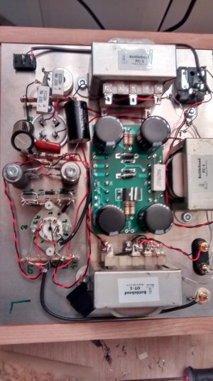
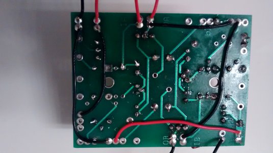
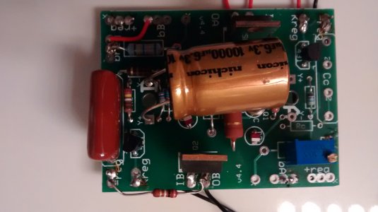
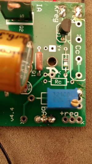
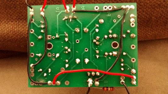
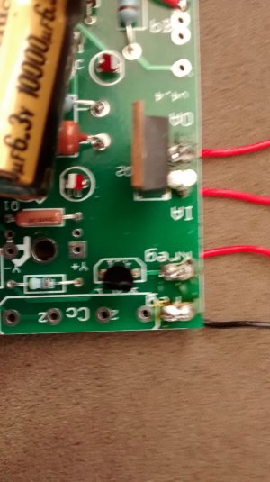
I am attaching some photos showing the resoldering and the steps to connect the pcb to B2, B4, B6, B8, 16U, 17U.
Any suggestions for getting OA back working?
Thanks again for your help....Take care...Dave
I couldn't wait until tomorrow. Kids are asleep!
I took off the pcb and resoldered all connections. Soldered the pcb to the correct locations..on the B terminals and 16 & 17.
Did my resistance checks:
reading Manual
-----------------------------------
1 infinity *
5 999 1K
6 1115 1118
7 247K 249K
9 infinity 124K *
10 0 0
11 infinity 3.0M
12 infinity 5.6M
13 0 0
14 infinity 9.2M
15 infinity 15M
16 increasing *
17 0 0
18 0 0
19 infinity 128K *
20 247K 249K
A1 1013 1027
A2 infinity *
A3 247K 249K
A4 1013 1028
B1 0 0
B2 7.96K 8.2K
B3 247K 249K
B4 296K 130k *
B5 0 0
B6 349K 177K *
B7 235 220
B8 1188K *
B9 0 *
Voltage checks:
OA 0 - 3 296
A2 447 440
OB 0 175
1 446 440
5 71 71
9 0 175
10 0 0
16 468 457
17 0 0
18 0 0
19 0 175
A1 73 74.1
A2 442 440
A3 0 0
A4 68 69.2
6V red 2.6 3.1
6V black 2.6 3.1
Kreg (A) 0 4.1
Kreg (B) 0 6.3
OA 0 300
OB 0 175
Darn it. No voltage now at OA!
Both LEDS on the A side lite up the B side LEDS do not lite up.I am attaching some photos showing the resoldering and the steps to connect the pcb to B2, B4, B6, B8, 16U, 17U.
Any suggestions for getting OA back working?
Thanks again for your help....Take care...Dave
Attachments
-
 IMG_20141107_201217056_HDR.jpg346.9 KB · Views: 138
 -
 IMG_20141107_204036299_HDR.jpg1.1 MB · Views: 118
 -
 IMG_20141107_203506887.jpg1.2 MB · Views: 122
 -
 IMG_20141107_203407007.jpg1.1 MB · Views: 119
 -
 IMG_20141107_201326854.jpg1.2 MB · Views: 103
 -
 IMG_20141107_201311210.jpg1 MB · Views: 130
 -
 IMG_20141107_201227601.jpg1.2 MB · Views: 111
I found this post from PJ for a person that was having 100V at OA:
"If the B side LEDs are not lit up, then there is no current running through them. From the diagram, you can see that the 100v you have goes through the LEDs, then 149K R2(B), then through 149K R2(B), then 2.49K R3(B) to ground. One of those connections is broken, presumably - or else the LEDs are in backwards.
It's the voltage dropped across the 2.49K resistor R3(B) that sets the shunt regulator voltage, so there's no surprise that voltage is not correct. It's possible (for example) that an error on this chain could damage the B-side 431 and short it, which would lead to about 100v on the shunt reg triode.
You can check the voltages on the varios resistors mentioned above, and on the 5670 pins 6, 7, and 8. This should give us more clues."
I have taken the voltages and am getting 0s across the board. Unless anyone has any suggestions... I think I am done. I have tried my hardest & done what research I can try to get this going. I don't know what else to do. I need someone to take this off my hands.
Its hard to take from listening to it for 30minutes and then feeling so far away from getting it to work. I was ready to buy a Beepre to pair this with but if I look at the photo it looks about 10 times harder.
If it is okay I think I am ready to send it in for professional assistance.
Take care...Dave
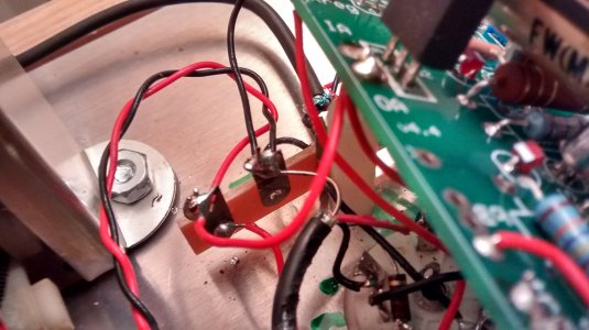
0V at OA would suggest that either the center leg of the MJE5731A isn't well enough soldered, or that two adjacent pads on the PC board got soldered together by accident when you went back to reheat the joints.
It's also entirely possible that one of the wires going to the board itself is a little loose, particularly the ground wire that would feed BA/BB.
-PB
It's also entirely possible that one of the wires going to the board itself is a little loose, particularly the ground wire that would feed BA/BB.
-PB
hi,
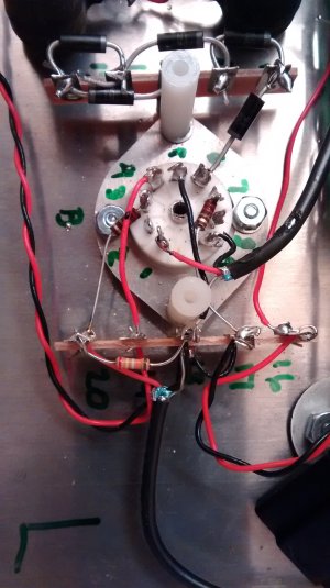
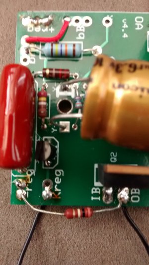
I took off the pcb again and warmed up the solder joints.
I am ready to reattach it to the Paramount. I am attaching pictures if anyone can see any problems.
Is there any way to test voltages without attaching it (ie. use a battery?). Probably not but wanted to ask.
I have used my meter to check continuity and everything seems ok. Does continuity indicate a good solder joint if you are measuring between the 2 solder joints (not the wires)?
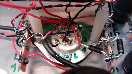
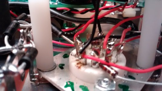
Here are the pictures. Really want to try to get this to work without sending it in but will if necessary.
Thanks...Dave
I took off the pcb again and warmed up the solder joints.
I am ready to reattach it to the Paramount. I am attaching pictures if anyone can see any problems.
Is there any way to test voltages without attaching it (ie. use a battery?). Probably not but wanted to ask.
I have used my meter to check continuity and everything seems ok. Does continuity indicate a good solder joint if you are measuring between the 2 solder joints (not the wires)?
Here are the pictures. Really want to try to get this to work without sending it in but will if necessary.
Thanks...Dave
Attachments
wullymc said:Is there any way to test voltages without attaching it (ie. use a battery?).
I have used my meter to check continuity and everything seems ok. Does continuity indicate a good solder joint if you are measuring between the 2 solder joints (not the wires)?
Here are the pictures. Really want to try to get this to work without sending it in but will if necessary.
The battery voltages would have to be pretty high to get the board to function, and you would have to simulate loads with large resistors, so it ends up getting complicated.
Other than some of the leads poking out on the bottom of the board being a bit long, it looks like that board should work well.
Do also bear in mind that a loose wire going from the board to the terminal strips/tube socket could cause your issue.
-PB
Thanks PB!
Well I reheated everything on the pcb and resoldered a couple of connections. i reattached everything to the Paramount.
Took voltages and everything is good! YAY!!!!
Waited 20 minutes, connected speakers and I have sweet music!! YAY! I listened for 1 hour.
Thanks again for your posts, without you and Paul Joppa's suggestions I would have been really stuck.
The only thing is when I power on the amp I get a "FFFFFFFFFFFFFFFF" sound for about 1 second. After it is fine and there is no problems afterwards. Do you have any idea what this could be?
Thanks again!...Dave
Grainger49
New member
Dave,
When you check continuity from the newly installed boards to the terminals or tube pins try checking from a component lead that is attached to the input/output/ground solder tab to the metal of the terminal or tube pin. Don't check from solder to solder. That can give you a false sense of security with the solder joints.
I have been bit in the butt by just this. So now I "ring out" from a component to component.
Good luck!
Thanks to everyone that contributed to this thread.
I am very happy to report that everything is working now! I have about 3 hours on both amps and everything is great. I had a problem with a FFFFFFF sound when I turned on the left one but that disappeared after 3 turn ons. I don't know if it was just something that needed to burn in a little bit? I don't know.
Anyway, thanks again for your patience with me! I am so happy!
Take care. Wishing everyone well.
Dave
There are some warm up noises with the Paramount, which shouldn't be of concern. There will be a little rustling usually, and actually a funny chirp that happens when the 431 regulator begins to operate.
-PB
-PB
Similar threads
- Replies
- 4
- Views
- 5K
- Replies
- 18
- Views
- 15K
- Replies
- 16
- Views
- 12K