Page 55 voltage check wrong need help again.

Kurthaudio said:
With tube in socket B and nothing in socket A I get tab 1: 216.8vdc  Tab 6: 0vdc

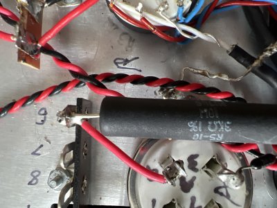
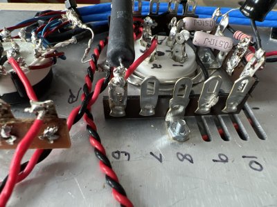
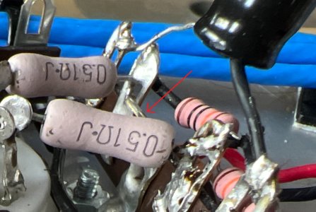
0V at terminal 6 is nearly an impossible result.  Are both ends of the 3K resistor well connected? Perhaps the solder joint at 6U isn't doing its job?

 
I just double checked and yes I’m getting 0vdc measuring from tab 4 (ground) to tab 6……….

The resistor measures 2995 ohms


P.S.
Just in case this is the first time in my life I’ve ever been wrong (lol) I reflowed all my solder joints. Related to socket A. Unfortunately Same results.
 

Attachments

  • image.jpg
    image.jpg
    1.7 MB · Views: 12
I cut out that resistor and soldered in a new one. Now I get about 215vdc on 6. And 216 on 1

Installed the tube and voltage drops to about 50 vdc @6
 
Can I see the other side of terminal 6?

With no tube in the socket, there's nothing to draw current through that resistor, so seeing 0V at terminal 6 indicates an issue with the amp that isn't tube related. 

 
That's terminal 5.

I definitely would not have just removed the resistor and arbitrarily replaced it.  That just adds more variables and you weren't able to measure any issues with it.
 
You asked to see the other side of terminal 6…… that would be terminal 1.

Here…. Here is a shot of all of it.
 

Attachments

  • image.jpg
    image.jpg
    1.8 MB · Views: 16
My apologies  for replacing the resistor I didn’t see the harm in it.

I am just trying to get this figured out. This has been going on for a few days now and I’m no further now then I was when I began. I don’t want to sound ungrateful for your help, I am but this is turning into a giant headache. If I didn’t have this amount of money tied up into this I’d of moved on with my life by now.
 
It would be helpful to see the back side of terminal 6.

If you had the configuration still with 0V at terminal 6, I would have next instructed you to measure the resistance to ground from terminal 6.  Now that opportunity is lost.

Are these the 5 lug strips we provided?  Very rarely the 5 lug strips we provide go out of stock and we have to provide alternatives, though it's pretty rare.
 
What is this?

To be honest, starting over and using stranded wire and the parts we provide would likely be the best idea.  I hadn't noticed the stranded wire till now, and it is absolutely the kiss of death on builds like these.
 

Attachments

  • beepre.jpg
    beepre.jpg
    290.8 KB · Views: 20
Could you explain why stranded wire is the “kiss of death” because that same stranded wire is working just fine on socket A

I’d be willing to bet you don’t want stranded wire used in these kits because one could easily have a small strand of wire make a connection where one shouldn’t.?. Something else I’ve been diligent about.

 
Yes, the strands go where you don't want them and the wire doesn't stay where you put it.  It's also both harder to make solid mechanical connections with stranded wire and tougher to move a wire if you don't put it in the right place.
 
Ok I just found something that is very important, I switched the wires from the regulator board and the problem followed suite. Now socket a has all the voltage issues socket b had and socket b is working correctly!!!!!


I think this says I have a bad regulator……right?
 
No, please resist the urge to blame parts as much as possible.

A bad regulator will result in not having 6.3V appearing between the output pins on the filament regulator board, is that what you're seeing now?

If one of the wires leaving that regulator board is touching something it shouldn't be, that could cause this problem. 
 
Nothing is touching anything it shouldn’t. No Cold solder joints and yes it’s making a sold connection.

Don’t worry I will not change anything g unless you tell me to

They both measure 6.2vdc exactly with nothing connected to them.

However I did notice the tube that has the voltage issue doesn’t get as bright as the one that’s working correctly……
 
Your regulators are doing their jobs.  This board does not have any reference to ground that will compete with the biasing resistors mounted by each socket, and your resistance readings also seem to confirm that this is still the case.


What I would do next is to pop both pairs of black/red twisted wires out of the regulator board, then measure DC resistance between terminal 4 and each of the four now empty output pads on the filament regulator board.
 
Back
Top