Page 55 voltage check wrong need help again.

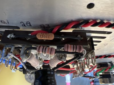
The parts used in this preamp are either the same quality or higher. The values have been checked double checked then rechecked time and time again.  I used my fluke 902 to measure most values I used my LCR meter to measure the rest.  to be 100% certain they are the correct values. I also had these exact voltages with the stock parts

I can re-install all the original parts if you would like to show I’m getting the exact same problem.

The tubes have not been installed backwards

The tube sockets are installed with larger pins to the back as stated in the instructions.

Let’s just assume  all values are installed correctly and all pins are in good contact. All solder joints are properly soldered. Would a set of bad tubes (possibly damaged from my first attempt) possibly cause this? If not……. What should be my next step to get this resolved?


If you swap the tubes from side to side, do the problematic voltages stay in the same place or migrate to the other side of the preamp?
 
OK, then you have an issue with the wiring on that side of the amp.

As I mentioned before, if A3 isn't well referenced to ground, that will throw things way off.  This is extra possible if there are cold solders or unsoldered joints.

If you replaced the cathode resistor with a different value (like 33 ohms instead of 330), then that would create this exact problem.
 
Agin. No cold solder joints ( I know how to solder very well) no un- soldered joints as shown in my last picture. 330 ohm is used.

I have built many kits. Several from Tubes for hi fi including 6 m-125 monoblock amps. Two Chinese phono stages, a bottlehead phono stage. Countless speakers over the last 20 years. I have made miles of soldered connections. I know what a cold joint is and I know what it looks like.

I understand you get a lot of solder issues on this forum. This is not a solder issue. Something else is going on here and to keep referring to a cold solder joint is not helping at all.
 
0.9V of bias and 45V on the plate means the 300B is drawing too much current.

You can temporarily solder in a wire between pin 3 on the 300B socket at terminal 4 to give the grid a solid ground reference to see if that changes anything.

Otherwise there is something amiss with the three resistors and the cap on 21-25.  The 0.9V would indicate a near short in that area. If you take the capacitor off that terminal strip, what is the DC resistance between pin 1 and ground? ...and pin 4 and ground?
 
With the 220 cap removed

Pin 1 - tab 3: 447.3 ohm
Pin 4 - tab 3: 449.2 ohm


Jumping pin 3 to tab 4 doesn’t change anything still .9vdc at 25 and 45vdc at 6


Voltage does not change with the 220 cap removed.

I tried it with the 220 cap removed. No change.

Jumped pin 3 to ground (tab4) with 220 cap removed. No change
 
There is something that's missing in all this, but I have no idea what it is.

0.9V across ~400 ohms is 2mA. 

The 130V you are measuring across the 3K plate load resistor is more like 43mA.

There should be no difference between these two.

These two measurements are contradictory, and when I see stuff like this, I tend to expect that a flaky solder joint is at work.  I know you are not going to be happy with that suggestion, but you have more or less ruled everything else out.  The only other explanations I could think of are ruled out by taking the bypass cap out and confirming appropriate resistance to ground from terminals 1 and 4 on the 4 pin socket. 

It may also help to get a photo of the 21-25 terminal strip with no cap installed, just to double check everything.

 
130V is the voltage across the 3K plate loading resistor.  130V/3K=43mA.

When looking at the 300B datasheet, 75V on the plate and 43mA of current does indeed happen with approximately 0V of bias.

The question with your preamp is why the bias voltage is so low (43mA drawn through that 330 ohm cathode resistor is 14V of bias!).  Something that would be super typical that we have run into in a situation like this is that the cathode bypass cap gets installed backwards, fails, but the builder will notice and reinstall it.  Instead of the DC operating current flowing through the 330 ohm resistor, it flows through the shorted cap.  In your case the problem exists without the cap there which further extends the mystery.

For your kit, can  you post the DC voltages between terminal 4 and:
21, 22, 24, and 25?
 
OK, here's what I can see from your measurements...

The 6.3V filament supply sits on terminals 22 and 24.  Those terminals are both connected to pin 25 by 130 ohm resistors.  6.3V divided by the 260 ohms (the two resistors in series) is 24mA, which would be the expected current with a 300B sitting in the socket but no current being drawn from the HV supply. 

Between 22 and 25, we see 3.4V, 3.4V/130R=24mA.

Between 24 and 25, we see 2.7V, 2.7V/130R=21mA.

These measurements tell me that nearly no current is being drawn across these resistors beyond just having the 6.3V filament supply active.

1.3V at terminal 25 indicates 4mA of cathode current, but this is a contradiction to what's going on with the HV side.

Just for curiosity's sake, if you run no 300B in the A socket with just a 300B in the B socket, what are the voltages at terminals 1 and 6?
 
Back
Top