One LED not burning [resolved]

Skipperrik

New member
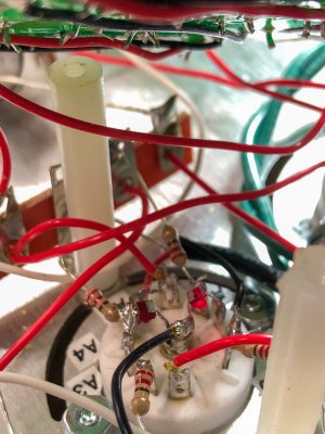
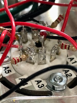
The LED between the ground pin and A3 refuses to glow. Re-flowing the solder hasn't brought it to life.

Below are the voltage specs/values:

C4S
IA  150/147.7
IA  60-90/71.2
KregA  3-6/7.6
bKregA  150/147.7
IB  150/147.8
OB  60-90/39.2
KregB  3-6/4.0
bRegB  150/147.8

High Current 1
1A  190/193.7
OA  150/149.7
bA  0/0.4
IB  0/0.3
OB  90-110/76.5
bB  150/147.9

High Current 2
1A  190/198.7
OA  150/149.6
bA  0/0.4
IB  0/0.5
OB  90-110/95.6
bB  150/149.6

If you could help me figure this one out I would appreciate it!
 
Can you post build photos?

In attempting to reflow the solder joint on the LED itself, it's very likely to be damaged.  There are many other causes for that LED to not light up, so I wouldn't just focus in on the LED itself.
 
Hit "Reply", hit "attachments and other options", there's a section that says "Attach:" and you can select your photos there.
 
The LED on the left is the problem. I also uploaded a photo of the board above the socket.
 

Attachments

  • IMG_4196-Edit 2.jpg
    IMG_4196-Edit 2.jpg
    854.9 KB · Views: 14
  • IMG_4197-Edit 2.jpg
    IMG_4197-Edit 2.jpg
    1.1 MB · Views: 12
Is A3 touching A4?

Again the LED itself isn't all that likely to be the issue, there are other faults that will cause the LED to not illuminate.
 
That LED looks to have a crack in it.  Generally a blown LED would produce a voltage of around 12-13V with the amp on, so if you see that you will need to replace that LED.  It's also important to reiterate that if an LED doesn't glow, there are loads of external causes that can produce that symptom, and the fragile LEDs don't handle a lot of extra heat from a soldering iron.

 
No, the tube is operating correctly with the conditions it's being given.  With the amp off, what is the DC resistance between A3 and terminal 3 with and without the tube plugged in?
 
Yeah that's the problem, not the tube.  I would go ahead and pop off the LED going to A3 and see if that resistance changes.
 
Okay. That's major surgery. I'll have to work on it tomorrow and let you know the results.

Thanks for your help! I think we're getting close.
 
Good morning, Paul.

I disconnected the leg of the LED attached to A3. The resistance now shows 0.L between A3 and terminal 3 with the tube in and out.

I also checked the continuity across the "bad" LED and there is continuity. There is no continuity across the "good" LED. Does that have any bearing on the problem?
 
Yes, it looked like there was possibly a crack in that LED as well.  To temporarily get your amp up and running, you can add a wire between A3 and A8 and you should find that all your voltages settle to appropriate values.  You can then replace that LED down the road as time permits.
 
Paul Birkeland said:
To temporarily get your amp up and running, you can add a wire between A3 and A8 and you should find that all your voltages settle to appropriate values.  You can then replace that LED down the road as time permits.

I am curious as to what the purpose of the LED's is. If you can substitute a wire between A3 and A8, will that work just as well long term in place of the LED's or are they working as some kind of safety fuse? I tried searching, but can't find any info on the function of the LED's.
 
The LEDs provide a constant 1.57V of drop from each 12AU7 cathode to ground.  If you tie both cathodes together, the amp will work but you may lose a bit of channel separation in the process. 
 
Back
Top