Just let me know which LED is out and what the voltages are on terminals 1-5.
You are using an out of date browser. It may not display this or other websites correctly.
You should upgrade or use an alternative browser.
You should upgrade or use an alternative browser.
Occasional popping sound - pictures and initial troubleshooting [resolved]
- Thread starter Mike1590
- Start date
I actually had a chance to check on these tonight. Lucky (maybe the wrong word) for me, the LED was already out before I started checking voltages. The problem LED is the one soldered onto pin A3. The issue appears to be with terminal 5. Here are my voltage readings now:
1. 81.2
2. 165.9
3. 0
4. 165.6
5. 148.5
1. 81.2
2. 165.9
3. 0
4. 165.6
5. 148.5
Measure the voltage at A3. If it's around 12V, the LED is damaged. A workaround for this is to connect a wire between A3 and A8 to restore operation.
If the voltage is 0V, that means the connection at A4/A5 isn't solid and needs more attention.
If it's something else, be sure to let us know.
If the voltage is 0V, that means the connection at A4/A5 isn't solid and needs more attention.
If it's something else, be sure to let us know.
Are both halves of the 12AU7 glowing? It is most likely that the solder joint at A4/A5 is loose.
It looks like the tube is fully illuminated, but I do have the top of the chassis upside down while I’m working on the undercarriage, so I don’t have the best view. I touched up A4/A5, but terminal 5 is still reading ~150V. Any other thoughts where this extra voltage could be coming from? I’d also be happy to take a picture of A4/A5, but I’m pretty confident in that soldering now.
What's the DC voltage at terminal A2?
The excess voltage is there because the tube isn't conducting.
The excess voltage is there because the tube isn't conducting.
Ah, makes sense. Here is a new photo of the connections on that socket - specifically A4/A5 shown. I will check on the voltage of A2. Side note, what is all of that orange/brown stuff? I never noticed all of it until I started working on the underside of the chassis again recently. As far as I know it isn't affecting performance at all, just looks messy/dirty & I'd like to clean some of it off if possible. Unsure if it's excess solder that's fallen off my iron while working maybe?
Attachments
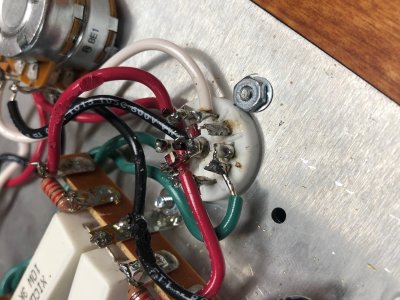
The brown stuff is flux. If you've used rosin core solder, that's totally fine to see there and you can use alcohol and a toothbrush to remove it.
0V at A2, an unlit LED at A3 and 0V at A3 and high voltage at terminal 5 would normally point to the A4/5 solder joint, but you say you have both halves of the tube glowing and the solder joint looks OK.
If the 22.1K resistor between terminals 4 and 5 isn't well connected, that would cause this problem also, as would a loose wire between terminal 5 and A1. If you happened to break off the plastic guide pin on the 6080 and you inserted it in one specific way that's not correct, you could also end up with high voltage on terminal 5, but this also seems unlikely based on the information provided here.
Ah sounds good. I will try to scrub some of that off once I get my amp working right again. I will check on those other connections tomorrow. You are correct that the 6080 guide pin is still in place, so I don't suspect that's the case either. I'll keep ya posted once I check on the connections you described and have had a chance to touch them up/re-measure voltage. I will also double check both halves of the tube are glowing by putting the chassis right-side up. Thanks again for your guidance on this!
I couldn't wait to tinker til tomorrow, so I played around a bit more tonight. Good news! The A3 LED now glows and the voltage on terminal 5 has gone down. There is still a low and constant buzzing in both headphone earpieces, but I think I'm getting closer to finding a fix. I did try tapping around with a chopstick a bit and didn't hear the same popping that I was hearing before - but having said that, I didn't mess around for too long, so it's very possible those sounds still exist.
Terminal 5 - 82.4V
A3 - 1.578V
A2 - 0V
A1 - 81.9V
If you have any more thoughts, I'd love to hear 'em! Otherwise, I'll plan to test for the popping sound a bit more tomorrow and report back.
Terminal 5 - 82.4V
A3 - 1.578V
A2 - 0V
A1 - 81.9V
If you have any more thoughts, I'd love to hear 'em! Otherwise, I'll plan to test for the popping sound a bit more tomorrow and report back.
For a low buzzing sound, I would check that all the 220uF capacitors are well connected and soldered to the terminal strips.
That did the trick!!! No more buzz and now I can move that smaller tube all around during playback without any popping sounds. You’re the man, Paul! Thanks so much for walking me through everything.
Edit: And most importantly, thanks for giving me the confidence to keep tinkering before throwing in the towel (and a bunch of money).
Edit: And most importantly, thanks for giving me the confidence to keep tinkering before throwing in the towel (and a bunch of money).
Darn, I jumped the gun. During music playback there was a loud pop and the left earphone completely cut out. At that time one half of the small tube also went out - presumably the one connected to A3 since that’s the one I’ve had trouble with. Should I try bypassing the LED and using a wire to bridge the pins like you suggested before?
Edit: I was able to confirm that the side of the tube that went out is the side connected to pin A3.
Edit: I was able to confirm that the side of the tube that went out is the side connected to pin A3.
If half of the tube stops glowing, it's not the LED.
The tube glows from AC voltage fed to it by the green twisted pair of wires. If one half of it stops glowing, the connection between A4 and A5 still isn't quite right.
You can remove all of the other wiring in the amplifier besides the green wires and the incoming AC wiring from the power switch and IEC module and the 12AU7 will still light up.
You can remove all of the other wiring in the amplifier besides the green wires and the incoming AC wiring from the power switch and IEC module and the 12AU7 will still light up.
Similar threads
- Replies
- 18
- Views
- 411
- Replies
- 0
- Views
- 276