No Sound from Right Channel

ScottAstroNut

New member
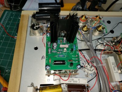
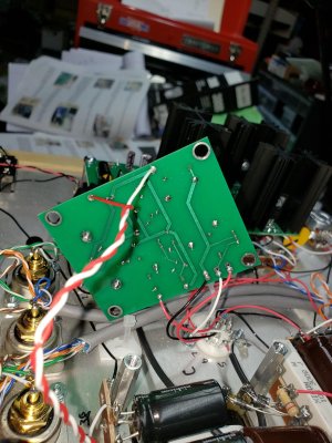
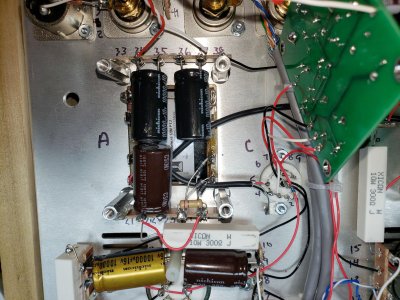
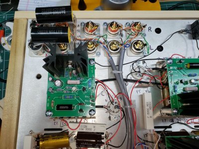
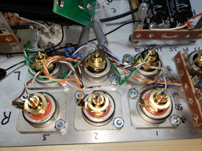
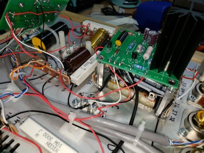
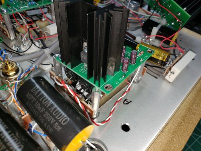
Hi All! I just finished my BeePre build, an have no sound at all coming from the right channel. The left channel seems to be working just fine.

Here's what I've done so far:

1) Checked all connections (interconnects, power, etc,) No issues found.
2) Swapped tubes. No effect. Right channel still dead but left channel works.
3) Checked tube glow. All tubes glow fine.
4) Checked LED's. All light.
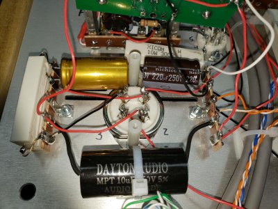
5) Inspected all wiring. Found one miswire: I had connected the 10 microfarad 250V capacitor to terminal 50 instead of 51. Fixed that. Found one iffy solder joint, resoldered that. For good measure I resoldered the center output for the right channel.
6) Did resistance tests several times. The only ones out of bounds were:

A4 at 3.0 ohms
B1 at 4.6 ohms
B4 at 5.4 ohms

7) Did voltage tests several times. The only ones out of bounds were:

Terminal 17 at 88.4V
B2 at 88.2V

At this point I am thoroughly flummoxed. Help would be appreciated.

Thanks!

Scott Burgess
 
Hey Scott,

I'm no expert, but I had the same problem when I first built my BeePre - I had miswired the A B C D terminals on the selector switch.  Have you tried all three pairs of inputs on the BeePre? If that doesn't make a difference, I'd double check all the red and black wiring at the input selector switch and the balance and volume pots.  I'd also test whether signal is getting to the grid of the right 300B.  With amp unplugged and cold, I'd connect one test probe to A3, set the input selector switch to input 1, set the meter for continuity, and connect/touch the other probe to the center pin of red/right rca input 1.  If the meter doesn't beep, I'd try to figure out where the break in connection is -- e.g., leaving one probe connected to the rca center pin, remove the other probe from A3 and put it on D (red) of the selector switch, and then on each of the lugs on the balance and volume pots to which a red wire connects.

If the red signal wiring is all good, I repeat the same continuity test for the signal ground, starting with one probe on terminal 8 and the other on the ground/-ve tab of red rca input 1.

Don;t know wither the above will help, but it's worth a shot.

cheers, Derek
 
OK. I did more poking around. In checking the wiring I found one major problem: the orange wire to the right side output was soldered to terminal 9U instead of 8U, and the orange-stripe wire was soldered to 8U instead of 7 U. I fixed this, with high hopes that I had found the problem. However, that did not solve the problem. Instead, I found another.

I did another voltage check, and I tried swapping the 300B's, but saw little difference between the two, so I don't think it's a bad output tube.

However, in touching the heatsinks on the C4S boards, I noticed that the sinks on the L channel were nice and toasty like I imagine they should be, whereas the sinks on the R channel side were much, much cooler. I also noticed that on the R C4S board, the two LED's on the A side of the board were noticeably dimmer than the LED's on the B side of the board. I also noticed that the tube on the R side was running significantly cooler than the L tube.

Redoing voltage checks I came up with the following anomalies:

Terminal 1 at close to zero volts (1.7V)
Terminal 6 at 187V
Terminal 10 at 189V (probably OK?)
Terminal 17 89.1V (probably OK?)
B2 at 88.2V

Something is obviously going on here. That terminal 1 is essentially dead and that terminal 6 is high means something isn't working. The question is, "What?" Ideas?

Thanks,

Scott
 
PB will know better, but it looks like there's an issue with the 10V filament supply.  It might to helpful to narrow down whether the problem is at the filament supply pcb or after it.

What DC voltage do you read between POS OUT and NEG OUT on the pcb?  You should see something close to 10V.
 
Hi Derek,

The voltage between POS OUT and NEG OUT on the filament supply is 9.85V, so close to nominal. The boards on both the R and L channels read that same voltage.

To me it seems that the A side of the R C4S board simply isn't getting power. So something before that?

Scott
 
More voltage checks.

The transformers are putting out the appropriate 213V (terminals 22 and 25, and 40 and 43), and both IA and IB seem to be getting about 180-190V each, measured directly on the board. OB is reading zero. OA (terminal 6) is reading a little high at 186V or so, on the R channel. The L channel reads nominal.

If OB is zero, why is it that the A side LED's are dim, whereas the B side LED's are bright?

Scott

 
I can't really speak to the C4S question, except to hazard a guess that the B+ regulation needs to be loaded by a conducting 300B, and your right side 300B is not really conducting b/c the filament isn't getting the voltage it needs -- but again, this is just a guess regarding the C4S/B+ issue.

But regardless of whether the filament supply issue is related to the B+ issue, I think you have a filament supply problem.  If the right side 10V DC filament supply was working properly, you'd see approx. 5V DC at terminal 1 relative to ground -- regardless of what was happening with the B+ circuit.  They are two different circuits. The fact that you see some voltage (approx. 1.7V DC) suggests a flaky connection somewhere between POS OUT, PINS A4 and A1, and terminals 1, 4 and 5.  If I were you, I would remove the board covering the A-side 4-pin socket and resolder all those connections.

cheers, Derek
 
Thanks, Derek. You certainly understand this circuit better than I, and I appreciate your wisdom.

I will go ahead and resolder the 4 pin socket.

Scott
 
Do you have the fat pins on the 4 pin socket on that side installed in the correct position? 

You have the Neg Out and -reg jumper on each board correct?  How about the red wire that leaves POS Out and goes up to the 4 pin socket?  On one side, it will go to pin 1 and the other side pin 4.

On each side, there should be a wire leaving the other empty filament socket (either pin 1 or pin 4) and going to the paralleled pair of 10W resistors. 

There's a connection in this system that isn't well soldered, or there's a miswire, but it's not easy to tell which.  If you were 100% certain that this voltage issue wasn't around before, I would say it's just a flaky connection that needs to be resoldered, or possibly a broken wire.

100% you need to focus on the low voltage side of things before worrying about the other issues that you have.
 
ScottAstroNut said:
Terminal 1 reads 4.86V and terminal 2 is still reading close to zero.
I would resolder the high current C4S board on that side.  You could also consider posting some build photos, as we might be able to spot something.
 
No wisdom, and very little understanding, I'm afraid.  For that you need PB. I've just played around with the filament supply a lot.
 
I have checked the tube socket, and it is oriented correctly. I also checked my wiring and didn't see any miswires. I resoldered all the connections around the 4 pin socket, the entire C4S board, all the connections around the power transformer under the filament board, as well as a couple of suspect joints on the filament board itself.

Put everything back together. Applied power. No changes. Terminal 2 still reads close to zero, and terminal 6 reads high. LED's on A side of the C4S board on the R channel still don't light.

I am enclosing pictures for you to help me spot any problems. Perhaps I have just looked at the same circuit too many times to see my faults.

Thanks!
 

Attachments

  • BeePre Build Pic 1.jpg
    BeePre Build Pic 1.jpg
    431.6 KB · Views: 9
  • BeePre Build Pic 2.jpg
    BeePre Build Pic 2.jpg
    435.4 KB · Views: 5
  • BeePre Build Pic 3.jpg
    BeePre Build Pic 3.jpg
    525.2 KB · Views: 7
More pictures.
 

Attachments

  • BeePre Build Pic 7.jpg
    BeePre Build Pic 7.jpg
    418.8 KB · Views: 2
  • BeePre Build Pic 6.jpg
    BeePre Build Pic 6.jpg
    380.2 KB · Views: 1
  • BeePre Build Pic 5.jpg
    BeePre Build Pic 5.jpg
    527.8 KB · Views: 3
  • BeePre Build Pic 4.jpg
    BeePre Build Pic 4.jpg
    180.9 KB · Views: 4
Still more pictures.
 

Attachments

  • BeePre Build Pic 8.jpg
    BeePre Build Pic 8.jpg
    548.1 KB · Views: 5
  • BeePre Build Pic 9.jpg
    BeePre Build Pic 9.jpg
    445.9 KB · Views: 6
  • BeePre Build Pic 10.jpg
    BeePre Build Pic 10.jpg
    468.5 KB · Views: 3
Could I get the IA, IB, and OB voltages of the high current C4S board on the side that's not working?

After that, can you repeat those measurements with no 300B in the socket on that side?
 
Back
Top