Hello, I just got done building the Crack and it was working great. Then I installed the Speedball upgrade and now I have no Left channel and the 2 LED's on the right side of the small board do not light up. It was like that when I first installed the small board but since then I have also installed the large board and all LED's on the large board are working. All my voltages and resistances are within limits besides there being a 15 volt differance between 0A and 0B on the small board, if that's any clue at all of whats happening. Not sure what to check next now so what do you guys suggest?
You are using an out of date browser. It may not display this or other websites correctly.
You should upgrade or use an alternative browser.
You should upgrade or use an alternative browser.
No Left channel with Speedball upgrade
- Thread starter Jaw22
- Start date
Can you post the actual voltage that you have?
Here's the current Voltages. Had a little different variation from OA and OB today, but still a difference between the two. I'm assuming that T5, A5, and OB have something weird going on since they are closest to the 10-15% limit.
All other terminals not listed are 0 Volts.
Crack Voltages Speedball Voltages
Terminal B Terminal A Terminal Small board Large Board
1. 85 1. 78 1. 85 OA. 85 OA. 105
2. 170 6. 85 2. 170 IA. 170 OB. 110
4. 170 3. 110 IB. 170 B+. 170
5. 78 4. 78 OB. 78
7. 110 5. 170
9. 105 6. 105
13. 170
15. 190
18. 75
19. 75
21. 208
Well, you can rest assured that the issue that you have is independent from the Speedball, and has crept up most likely from a solder joint that wasn't quite all the way solid, which is now giving you some troubles. Some common places for this to happen are the solder joints on the headphone jack, RCA jacks, and potentially at pins 2 and 7 on the 9 pin socket.
-PB
-PB
I got done re-flowing all the solder joints and still have the same problem and voltages. The right 2 LED's on the small board still don't glow and still no Left channel. I measured the Voltages on the LED's and the Left, next to input jack, D1 has 170, D2 170 - Right, next to Potentiometer, D1 170, D2 170 no stripe and 80 on the silver stripe. I re-flowed the solder on the small board and it made no differance either.
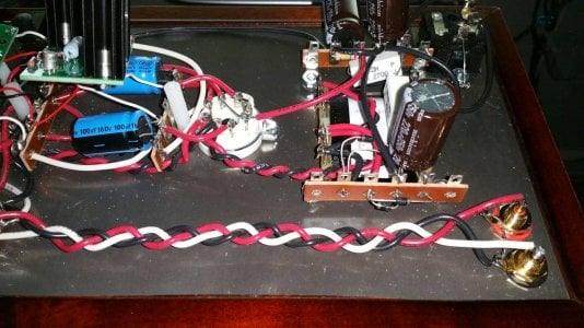
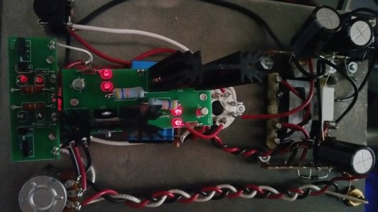
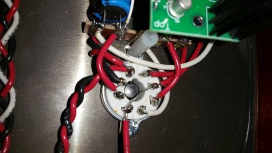
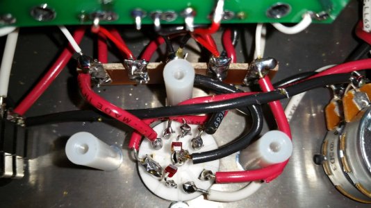
Your voltages tell us that the boards are operating properly. Can you post some photos of the build?
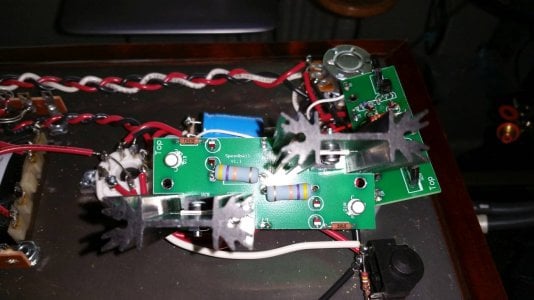
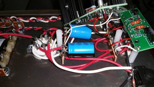
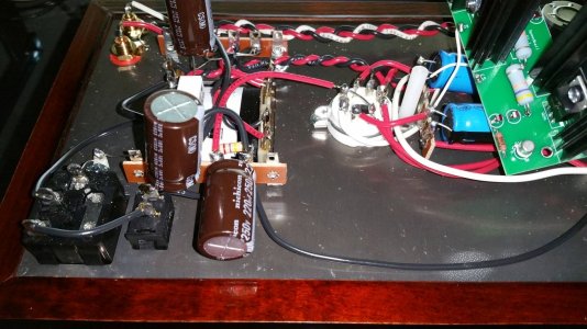
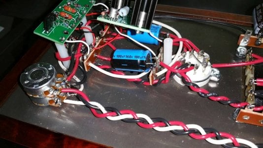
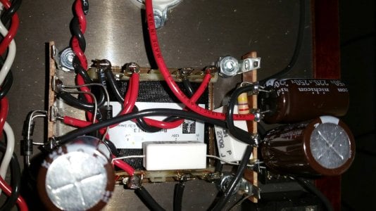
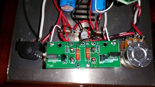
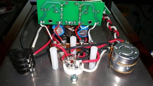
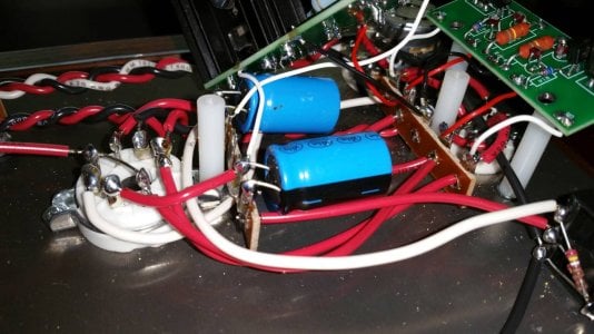
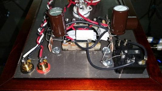
I do have sound in the both channels now after noticing I had my left RCA unplugged yesterday when I tried it again, but still have more sound in the right than the left. Here's some pictures and hopefully I got all the terminals you need to see.
Also there's a lot of EMI noise from my computer when I go past 40% volume on the crack potentiometer but my computer volume doesn't make a difference. I think it's probably just interference from the computer but it's quiet when the headphones are directly plugged into the card. I'm running an ASUS Essence STX in my computer and have RCA's to the Crack.
Also there's a lot of EMI noise from my computer when I go past 40% volume on the crack potentiometer but my computer volume doesn't make a difference. I think it's probably just interference from the computer but it's quiet when the headphones are directly plugged into the card. I'm running an ASUS Essence STX in my computer and have RCA's to the Crack.
Attachments
-
 20160526_155902.jpg153.2 KB · Views: 53
 -
 20160526_162542.jpg83.4 KB · Views: 37
 -
 20160526_160154.jpg105.9 KB · Views: 36
 -
 20160526_160120.jpg124.1 KB · Views: 42
 -
 20160526_160052.jpg108 KB · Views: 38
 -
 20160526_160013.jpg145.1 KB · Views: 33
 -
 20160526_155940.jpg166.6 KB · Views: 65
 -
 20160526_155909.jpg148.4 KB · Views: 38
 -
 20160526_160203.jpg134.3 KB · Views: 37
 -
 20160526_160139.jpg121.5 KB · Views: 73
 -
 20160526_160112.jpg119 KB · Views: 35
 -
 20160526_160032.jpg116.2 KB · Views: 77
 -
 20160526_155958.jpg135.4 KB · Views: 49
 -
 20160526_155924.jpg133.1 KB · Views: 51
Can you very carefully measure the voltage at A3?
Despite the lack of LED glow on one side of the small PCB, your small board does appear to be working properly. To double check, you can desolder the wires at OA and OB, twist the board 180 degrees, then reattach the wire that went to OA to OB, and the wire that went to OB to OA, then remeasure the voltages and check for odd behavior.
Okay, wierd things are happening now. Haha
First, I reversed the 2 wires OA and OB on the small board and it just reversed the voltages I had as well as Left being louder than right. Then I put the wires back to the right holes and now I have 160 Volts on OA, 85 Volts on OB and both D1 LED's lighting and both D2 LED's not. OA's LED obviously much brighter than OB's.
Worked great before I added the speedball, so maybe I should be banned from PCB's, or just my bad luck I have all the time with electronics.
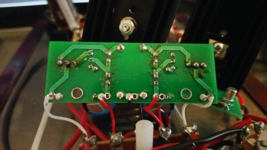
Resolder all the solder joints on the bottom of the PC board, paying extra attention to reheating the center leg of the MJE-350.
With your 160V from A6, do you also have both socket LED's glowing? If so, I'd still suspect that you have an MJE350 that isn't all the way soldered in.
I resoldered the MJE350's 3 times and all 3 times I had the same voltages and no resistance from all 3 of the transistor connections to where they go, like OA to middle transistor wire.
OA is 160V, OB is 90V, IA and IB is 160V. The large board OA is 110V, OB is 160V and B+ is 160V.
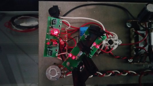
All parts on the small board have 160V including the LED's, besides the middle wire on the O2B transistor with 90V, but the LED next to the O2A transistor isn't lighting and the one above it is very bright.
OA is 160V, OB is 90V, IA and IB is 160V. The large board OA is 110V, OB is 160V and B+ is 160V.
All parts on the small board have 160V including the LED's, besides the middle wire on the O2B transistor with 90V, but the LED next to the O2A transistor isn't lighting and the one above it is very bright.
Attachments
Just to be thorough, can you remove the 6080, then test the amp with just the 12AU7 installed. You'll only be interested in the OA/OB voltages. (IA/IB will be higher than expected)
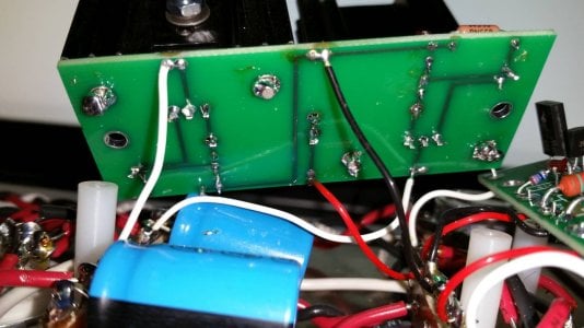
Can you flip the board up and post a photo of the bottom?
I would replace the white wire from OA to terminal 1.
-PB
-PB
Similar threads
- Replies
- 11
- Views
- 5K
- Replies
- 9
- Views
- 3K