No good after speedball upgrade

hardisondan

New member
Hello,
I'm back after a long hiatus. I looked up my last post and it was 2014. That was when I finished my Crack. After some newbie challenges, I got there and I was really happy with it. It sounded great, and I was constantly amazed at how dead quiet it was, even with volume turned way up there was no background hum or noise of any kind. I PROBABLY SHOULD HAVE LEFT IT ALONE.

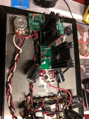
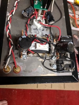
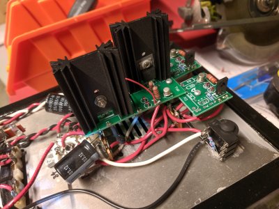
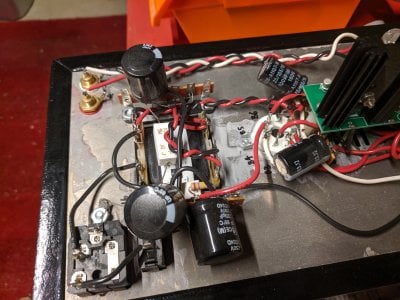
Anyway, I attempted the speedball upgrade and it was a big fail. Main tube glows, but no sound. No LEDs on near the small tube. It has been in mothballs for the last five years.

Now I am ready to tackle it again. I have a shiny new soldering station and a new can-do attitude. I am going to re-do the tests to try and narrow it down. I have three questions:

- Firstly, if you had to bet on it, what would be the number one thing people stuff up when adding the speedball?
- Do the resistance check measurements in the Crack assembly manual apply post-speedball? I don't think there was a resistance check list in the speedball assembly manual (but I could be wrong)
- I just noticed on re-reading the Crack manual, that the section on voltage checks mentions they were taken at 110V AC. I am in Australia, so 240V. Does this have any bearing on expected voltage test results?

You might be hearing from me more.
Dan
 
hardisondan said:
- Firstly, if you had to bet on it, what would be the number one thing people stuff up when adding the speedball?
Which Speedball do you have?  We made some revisions and the new version has one small, narrow PC board up front and a big board in the middle of the amp, while the old Speedball has two square boards up front.  The very long list of mistakes people made with the early Speedballs precipitated nearly all of the changes we made with the second iteration, so this is an important piece of information.
hardisondan said:
- Do the resistance check measurements in the Crack assembly manual apply post-speedball? I don't think there was a resistance check list in the speedball assembly manual (but I could be wrong)
The voltage checks are absolutely critical.  There isn't a useful recommendation that will come about repairing your amp until you post the voltages on terminals 1-10.

hardisondan said:
- I just noticed on re-reading the Crack manual, that the section on voltage checks mentions they were taken at 110V AC. I am in Australia, so 240V. Does this have any bearing on expected
voltage test results?
The version 1.0 of the Crack had a 120V or 240V power transformer.  If you wired up the 120V power transformer to 240V mains, many other things would've failed immediately with your build, so we don't have to worry about that.

hardisondan said:
You might be hearing from me more.
I hope so, another thing you could do is to post some photos of your build.  Some things are pretty easily spotted immediately.
 
PBs suggestions are right on. The only thing I would add is to do a few things before you turn the amp back on and check voltages -

With this much time away from the amp what I would suggest first is going through the Speedball manual again and checking that each step was done correctly.  Time away from a project like this can actually help you to spot something you might not have seen when you had just finished the build and were troubleshooting.

While doing this look for good solder joints on all the connections. Make sure the center pins of the big transistors are adequately soldered. Make sure the new wires that connect the boards to the circuit are attached to the correct terminal and pads. Be sure the insulators and hardware that mount the big transistors to the heat sinks have been installed the right way.

After you have confirmed that stuff the check the voltages PB has asked you for and post them here.
 
Thanks Paul.

What I meant was since the voltage test result section mentioned that they were done in the 110V environment, does that imply they might be different in a 240V environment. Sounds like no. I will definitely do the voltage tests and post results ASAP.

And is there a list of resistance check test/results for performing after adding the speedball?

See photos. Any advice appreciated (be kind about my sloppy work)

Cheers


Attachments

  • IMG_20191029_142624.jpg
    IMG_20191029_142624.jpg
    3.3 MB · Views: 54
  • IMG_20191029_142631.jpg
    IMG_20191029_142631.jpg
    3.1 MB · Views: 39
  • IMG_20191029_142703.jpg
    IMG_20191029_142703.jpg
    3.1 MB · Views: 37
  • IMG_20191029_142713.jpg
    IMG_20191029_142713.jpg
    3.7 MB · Views: 31
hardisondan said:
And is there a list of resistance check test/results for performing after adding the speedball?
You need to measure the voltage on terminals 1-10.

I notice from your photos that one of your 270 ohm resistors is cooked.  With the older version of your Speedball, it was incredibly common that people didn't properly mount the TIP50s to the heatsinks, and this would cause them to touch and ground out, which would cook that particular resistor.  In this case, you can measure the voltage from terminal 12 to each of the metal tabs on the TIP50 heatsink.  If you get a low resistance there (under about 100 ohms), then your TIP50 transistors are not properly mounted and you'll need to take the mounting kits off and remount them according to the instructions in the manual.

 
Paul Birkeland said:
you can measure the voltage from terminal 12 to each of the metal tabs on the TIP50 heatsink.  If you get a low resistance there (under about 100 ohms), then your TIP50 transistors are not properly mounted and you'll need to take the mounting kits off and remount them according to the instructions in the manual.

@PB: did you mean to write "measure the resistance", not voltage?
 
Paul Birkeland said:
I notice from your photos that one of your 270 ohm resistors is cooked.

I'm lost. I just checked the resistor values on my stone age Speedball. I've got 4 x 22.1k. They are the ones standing upright forming the two pairs. 2 x 31R6 1/8W next to the heatsink. 2 x 150k, one each on the small boards, 2 x 237R also there. Dan's Speedball boards look to be the old ones just like mine.

The center pins on some of the large transistors look like they might not be properly soldered.
 
grufti said:
I'm lost. I just checked the resistor values on my stone age Speedball. I've got 4 x 22.1k. They are the ones standing upright forming the two pairs. 2 x 31R6 1/8W next to the heatsink. 2 x 150k, one each on the small boards, 2 x 237R also there. Dan's Speedball boards look to be the old ones just like mine.
The 270 ohm resistors are in the power supply; they are the big white cement resistors mounted by the power supply.

If a tip50 is improperly mounted, it grounds the cathode(s) of the 6080, and the 6080 will draw current until something gets hot until something burns up.  That thing that burns up is the 270 ohm resistor that is mounted over the power transformer.
 
Thank you, Paul. I'm no longer lost.

I just re-checked the posted images. Did you identify that defect because of the discoloration/blueing on the wire and the slight cracks around the entry point of the wire?
 
Thanks everyone for your assistance.

Paul Birkeland said:
You need to measure the voltage on terminals 1-10.

I notice from your photos that one of your 270 ohm resistors is cooked.  With the older version of your Speedball, it was incredibly common that people didn't properly mount the TIP50s to the heatsinks, and this would cause them to touch and ground out, which would cook that particular resistor.  In this case, you can measure the voltage from terminal 12 to each of the metal tabs on the TIP50 heatsink.  If you get a low resistance there (under about 100 ohms), then your TIP50 transistors are not properly mounted and you'll need to take the mounting kits off and remount them according to the instructions in the manual.

Resistance from 12 to 1-10 are all "0L", except 3 which is 0 ohms, and 8 which is 1 ohm.

Resistance from 12 to the fins on the Speedball heatsinks is 0L. Not sure if that's what you meant by tabs?
 
OK, that's a good sign with the resistances, go ahead and move on to voltage checks.

The forum will give that error if the photos are huge, I use a simple resizer to reduce them by 80% or so if they are too big.
 
hardisondan said:
Resistance from 12 to the fins on the Speedball heatsinks is 0L. Not sure if that's what you meant by tabs?

Just checking: when you say you measured resistance between terminal 12 and the "fins" of the heatsink, did you touch the lead to the body of the heatshink itself (big black block of finned aluminum) or to each of the skinny silver legs (what PB called "tabs") that are soldered to the pcb board?

I imagine you did the latter (the legs/tabs), which is what I think PB wanted?, but thought it might be good to be sure.

cheers, Derek
 
Deke609 said:
Just checking: when you say you measured resistance between terminal 12 and the "fins" of the heatsink, did you touch the lead to the body of the heatshink itself (big black block of finned aluminum) or to each of the skinny silver legs (what PB called "tabs") that are soldered to the pcb board?

I imagine you did the latter (the legs/tabs), which is what I think PB wanted?, but thought it might be good to be sure.

cheers, Derek

I actually did both as I was unsure, but same reading either way.  Thanks Derek
 
Paul Birkeland said:
OK, that's a good sign with the resistances, go ahead and move on to voltage checks.

The forum will give that error if the photos are huge, I use a simple resizer to reduce them by 80% or so if they are too big.

So do the voltage checks as per the manual? Are they still valid given my cooked 270 ohm resistor?
 
The voltage checks will give us a pretty complete picture of what's going on with your amp.  It will be helpful in identifying any potential problems, including issues with that resistor, though based on its appearance it is probably still functional.
 
Paul Birkeland said:
The voltage checks will give us a pretty complete picture of what's going on with your amp.  It will be helpful in identifying any potential problems, including issues with that resistor, though based on its appearance it is probably still functional.

Thanks Paul. I have to go away for a few days.. just when I was getting excited about this. I'll resume next Wednesday. I really appreciate your taking the time to help.
 
OK here goes. They are nothing like the manual.. Voltages at:
1:  0.4
2:  0.01
3:  0
4:  0.005
5:  0.4
6:  0
7:  1.3
8:  0
9:  0.8
10: 0

On a side note. I bought some new leads for my multi meter because the ones it came with didn't have alligator clips. Then I forgot which terminal was which colour. After some quick research I found that black goes in the terminal marked COM (for common I guess?). But then nearly all the readings had a negative in front of them. I read that it doesn't really matter, so I switched the leads around again to test. I left the negative off my measurements above.


Back
Top