Doc,
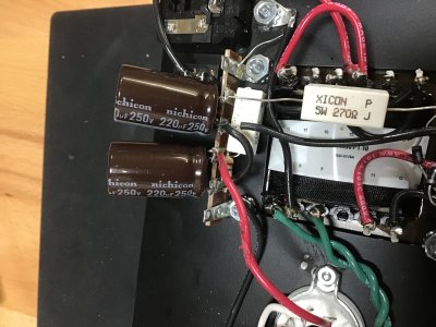
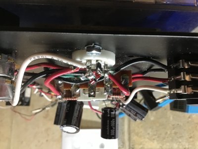
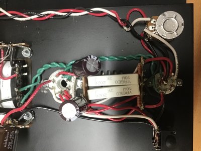
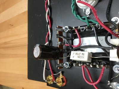
The reading between pin B7 and B8 is 0.1 ohm.
PB,
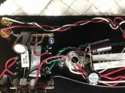
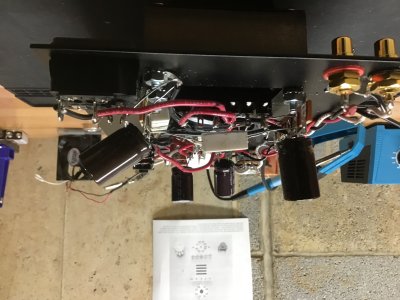
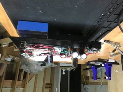
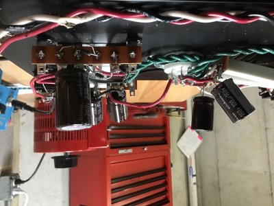
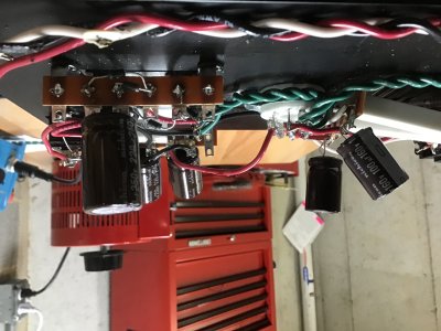
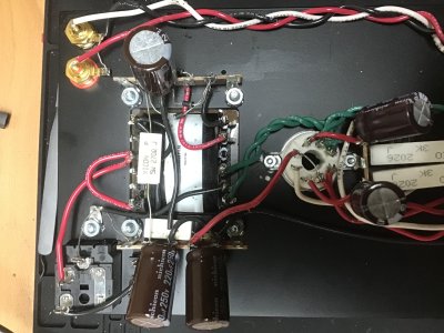
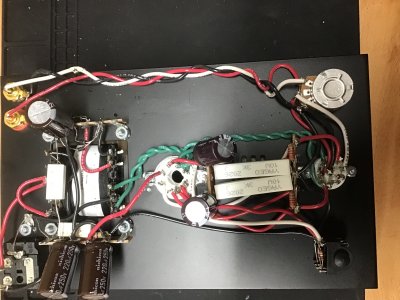
I set the chassis plate on the base right side up, plugged it in, and both tubes were glowing after a few minutes. However, when I removed the chassis from the wood base and turned it on its side, only the 6080 glowed. The socket appears to be installed correctly and I can assure you that the plastic keyway is fully intact. The wires going to the 9 pin socket appear to be securely soldered in place. The LEDs are not lit.
I measured the voltages and they are way off as follows:
1. 205.1 V
2. 205.5 V
3. 96.6 V
4. 205.3 V
5. 197.2 V
6. .3 mV
7. .3 mV
8. 0 V
9. 92.6 V
10. 92.7 V
I disconnected the test lead and put the chassis back into the wood base. The 12AU7 is not glowing. The 6080 glows when first turned on and then goes dark after about 30 seconds.
Let me know what you think. I do appreciate your help.
John
The reading between pin B7 and B8 is 0.1 ohm.
PB,
I set the chassis plate on the base right side up, plugged it in, and both tubes were glowing after a few minutes. However, when I removed the chassis from the wood base and turned it on its side, only the 6080 glowed. The socket appears to be installed correctly and I can assure you that the plastic keyway is fully intact. The wires going to the 9 pin socket appear to be securely soldered in place. The LEDs are not lit.
I measured the voltages and they are way off as follows:
1. 205.1 V
2. 205.5 V
3. 96.6 V
4. 205.3 V
5. 197.2 V
6. .3 mV
7. .3 mV
8. 0 V
9. 92.6 V
10. 92.7 V
I disconnected the test lead and put the chassis back into the wood base. The 12AU7 is not glowing. The 6080 glows when first turned on and then goes dark after about 30 seconds.
Let me know what you think. I do appreciate your help.
John