New Builder learned so much from his mistakes he now wants to rebuild

Agweeks

New member
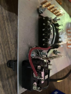
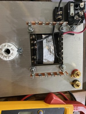
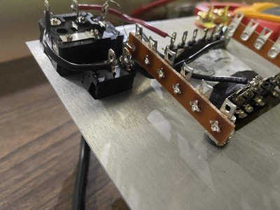
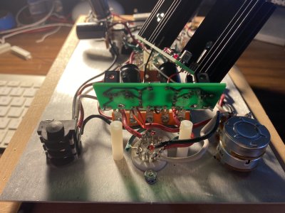
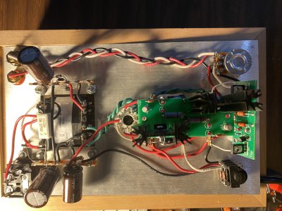
I have learned so much about amp building with my amp "build".  I purchased a crack kit for this purpose.  All the Youtube videos on soldering in the world just can't replace real-world experience.  The initial build was/is so poor that it was/is riddled with problems.  It has become a game of whoppamole.  One problem solved creates another.  I chase down one problem, reflow/resolder every visibly poor or weak solder joint in the process, sometimes repeatedly, trying to eradicate all of the problem and create another problem in the process.   

I now know that I wasn't making a good mechanical connections with the leads and wires prior to soldering.

I wasn't getting my iron hot enough.

I was using way too much solder.

I was not allowing the flux to cook off after having the solder flow.  I removed to iron too quickly, creating cold joint.

I didn't know what a good joint looked like. 

I didn't know that flux is why the solder flows across the surfaces of all the parts and that is why you heat one side of the joint and add solder to the other side.  I've seen this happen over and over now. 

All of that being said, I would like to disassemble the amp, clean all the terminals and rewire the whole thing, now that I know what I'm doing.  I have a solder sucker, the copper ribbon for removing solder and new hook up wire.  My thinking is that I will have a more stable, better looking amp. It might even sound better.  Who knows.

Can anyone give me any suggestions on how best to clean the connections?  Am I on the right track?  Is this overkill?

 
By the way, I was inspired to do this because I built a Stereomour II kit this week with my new skills and was able to complete it without any problems.  I wired it up.  It tested out correctly.  It just works. 
 
I would contact replacementparts(At)bottlehead(dot)com and ask for a new Crack wire, hardware, and electronics bag.  Take everything off the chassis besides the power transformer, and carefully remove the wires from the power transformer. 

This will not be the least expensive path, but you'll end up with the best results from a fresh start, and a lot of the parts and especially the wires you have now aren't going to do well being pulled out of the amp. 
 
So I finally got around to ordering the parts and hardware like you suggested.  i followed your instructions and have begun to rebuild.  I'm to the power transformer secondary test.  I'm getting almost no power for terminals (7 and 9) and (11 and 12). 

The initial power testing has checked out.  The power reads 120 across for the switch and using terminals 8 and 18.  Using terminal 13, I also get 120. 

I'm afraid I've blown my transformer.  Please allay my fears.

AGW
 
Maybe post a pic of the transformer wiring.

And if your meter does not auto-range, double check that you have selected the next highest voltage value above the target measurement. E.g., if looking for 6.5 VAC, select 20 VAC.  For 175 VAC, select 200 VAC.  And double check that the meter is set to AC not DC.

cheers, Derek

 
Thank you for the reply.  My Fluke meter was set to AC voltage and auto ranges.  Here are photos of the transformer connections:
 

Attachments

  • amp 1.jpg
    amp 1.jpg
    1.2 MB · Views: 24
  • amp 2.jpg
    amp 2.jpg
    1.6 MB · Views: 24
  • amp 3.jpg
    amp 3.jpg
    1.5 MB · Views: 16
There are four steps in the manual to wire the power transformer for 120V.  You have done one of the four correctly, one of the four incorrectly, and you haven't even done the other two. 

Please slow down and work more carefully. 
 
Wow. I’m sorry for wasting your time. I must have skipped a page. I’m reading it from my computer because I’m too confident now. I’ll go back to printing the out. Thank you.
 
My kit came out OK but I know I can do better, so I got some parts to replace too. Then I ordered two more amps while I was at it. It is a fun learning experience.

Bottlehead has some how-to posts and videos. I found them very helpful. It’s hard to understand what a proper solder joint looks like from 1 or 2 still angle shots.
 
So I wired up the crack successfully.  I listened to it for a few days.  Everything was fine.  Then I decided to go ahead and wire up the speedball modification.  I installed the first board successfully.  Everything checked out.  I listened to a whole song.  The second board (with the large black heat sinks) is now installed.  However, only the left channel plays.  I've now discovered that when I put the board together months ago I soldered in a jumper at D2 because I kept fiddling with it and that diode broke one of its leads.  Is that what the problem is?

Thanks,

AGW

 
I replaced it with a jumper because it won’t work with a broken LED. I had hoped the light was just so I could tell if the circuit was working.

I’ll order a new one.
 
I apologize if that came across as being rude.  The LEDs serve as a precise voltage reference in the C4S circuit.  You could probably replace each one with a D cell battery, but other than that they really need to be those specific parts and nothing else. 
 
Paul Birkeland said:
  The LEDs serve as a precise voltage reference in the C4S circuit.

I suspect that the confusion stems from the fact that elsewhere in the circuit (cathode bias of the 12AU7) the HLMP6000 can be replaced with a jumper and numerous builders who've toasted their LEDs have been so advised [Edit - just to clarify: the jumper doesn't replace the LED, but obviates to need for it by making both cathodes share the same bias from the working LED]. Unless one understood that the same diode used in different parts of the circuit performs different functions, one might assume that the diode can be replaced with a piece of wire in all cases.  I might have made that same mistake just a year ago before I learned a bit about biasing transistors (which, unlike the 12AU7, won't "turn on" at all without proper biasing).

cheers, Derek
 
Thank you Derek for the explanation. I am rebuilding this amp because it was the first amp I ever built. I had a lot of trouble but learned a ton. I think I ended up breaking all of the LED’s because I soldered and resoldered everything over and over trying to fix it. I now seem to recall being told I could use a jumper in place of the LED’s for the regular amp circuit. I am sure I simply assumed it was ok to do the same for the speedball mod. So again, thank you for the explanation. I’m new to amp building and have a great deal of desire to learn.

I saw your edit and yes! That’s it. I was told I could use one diode and solder two jumpers to it.
 
Agweeks said:
Thank you Derek for the explanation.

Don't take anything I say as gospel. On my best days I barely know what I'm talking about - just read any of my posts and the responding corrections from PB and PJ for verification.  ;D

I’m new to amp building and have a great deal of desire to learn.

You and me both, brother!  And if I wasn't so fascinated by it all, I would have given up 2 years ago b/c the physics of electronics is just not intuitive to me. But I am SLOWLY starting to wrap my head around the basics.  Good luck with the amp.

cheers, Derek
 
I received the my leds and replaced the jumper in the big board for the speedball mod.  The amp worked fine using my Mac, streaming Tidal.  Then I attempted to use my new Schiit Bifrost DAC plugged into my iphone (using an apple camera adapter) and PC laptop.  Now the two leds on the 12AU7 don't light up and I get no audio out of it.

I have reviewed all of the connections, reflowed several of the joints and even replaced the leds connected to the tube. 

The voltage to is as follows:

Terminal

1.  180
2.  184
3.  0
4.  184
5.  179
6.  fluctuates at a low level
7.  178
8.  0
9.  177
10.  fluctuates at a low level

I'm going to post a photo of the amp in another post below.

Thank you in advance.

AGW
 
Back
Top