Need to identify version and get manual for used Crack + Speedball

manicmidget

New member
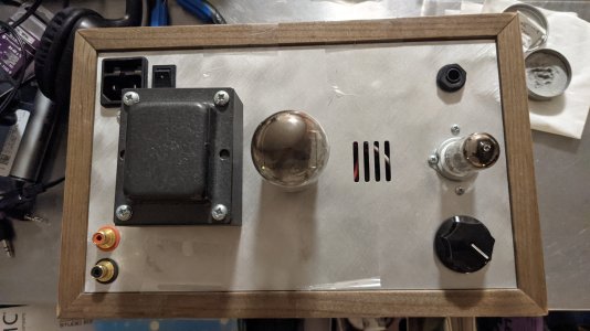
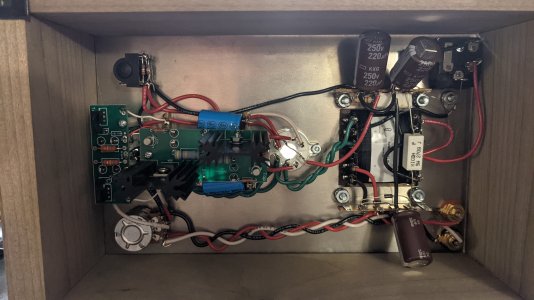
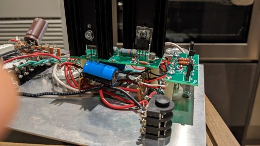
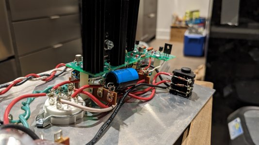
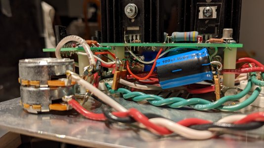
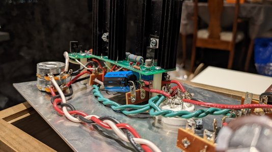
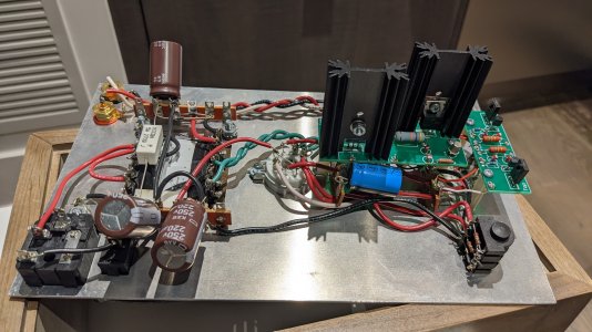
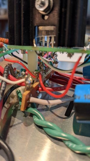
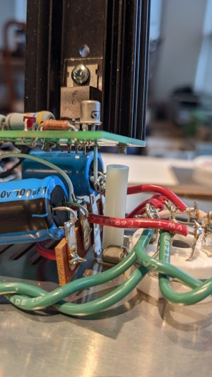
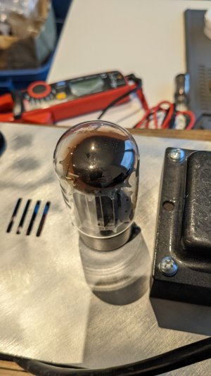
Hi, I just purchased a broken Crack w/ Speedball to repair it myself, and the seller didn't have the manual as he had purchased it pre-built. It's also unclear which version(s) the Crack and Speedball are. Hoping someone from Bottlehead can contact me to help. Thanks very much!
 
Thanks for replying! Please let me know if you need more photos.
 

Attachments

  • PXL_20210529_032236967.jpg
    PXL_20210529_032236967.jpg
    2.8 MB · Views: 49
  • PXL_20210529_032308755.jpg
    PXL_20210529_032308755.jpg
    2.7 MB · Views: 72
That's a Crack 1.1.

On the 5 lug strip mounted by the 9 pin socket, the outer pair of terminals should measure around 75V DC with the amp running, the inner pair of terminals should be around 175V DC with the amp running, and the middle terminal sits at 0V.

On the 5 lug strip mounted to the octal socket, the outer terminals should be 0V, the inner pair of terminals will be roughly 100V, and the middle terminal 0V.

This is about all of the information that you would get out of the manuals.  You're also missing the fuse holder, but the fuse looks to be installed at least.
 
Thanks very much, that's good to know.

However, I'd still like a copy of the manual if possible -- I'm fairly new to the hobby but I'm already hooked on mods & DIY and I'm trying to learn how the circuitry works and such. Is there someone I could ask?

(And is there some way I can get a replacement fuse holder?)
 
Did you get this amp sorted out? Looking at the pics I'm not seeing solder on the resistors on the speedball circuit boards. If I were you I'd re-solder ever joint on the amp.
 
Paul Birkeland said:
On the 5 lug strip mounted by the 9 pin socket, the outer pair of terminals should measure around 75V DC with the amp running, the inner pair of terminals should be around 175V DC with the amp running, and the middle terminal sits at 0V.

On the 5 lug strip mounted to the octal socket, the outer terminals should be 0V, the inner pair of terminals will be roughly 100V, and the middle terminal 0V.

Hi, I realize it's been almost exactly 1.5 years since I posted this -- life seriously got in the way.

I did the readings, and the 9-pin socket lug strip is actually quite wonky -- I'm getting ~0V on the outer pair, one of the inner pair reads ~110V and the other ~0V, and there's nothing soldered to the centre pin.

For the 8-pin socket lug strip, I'm sort of getting the values you learned for the 9-pin, i.e., ~75V outer pair, ~195V inner pair, and ~0V centre pin.

(I'm assuming the volume potentiometer doesn't matter here, but it was at the lowest position.)

I'd really appreciate any (more) help you could provide. Thanks in advance!
 
Thanks for the super quick reply! I tried to do my best with camera angles. Please let me know if you need more photos.
 

Attachments

  • PXL_20221128_040214972.jpg
    PXL_20221128_040214972.jpg
    1.6 MB · Views: 6
  • PXL_20221128_040203297.jpg
    PXL_20221128_040203297.jpg
    1.5 MB · Views: 5
  • PXL_20221128_040146970.jpg
    PXL_20221128_040146970.jpg
    1.8 MB · Views: 4
  • PXL_20221128_040135163.jpg
    PXL_20221128_040135163.jpg
    1.9 MB · Views: 3
  • PXL_20221128_040115175.jpg
    PXL_20221128_040115175.jpg
    2.4 MB · Views: 3
  • PXL_20221128_040105528.jpg
    PXL_20221128_040105528.jpg
    945.2 KB · Views: 12
charnich said:
Did you get this amp sorted out? Looking at the pics I'm not seeing solder on the resistors on the speedball circuit boards. If I were you I'd re-solder ever joint on the amp.

Hi, sorry for taking so incredibly long to respond. The resistors are indeed soldered, just on the underside.
 
manicmidget said:
one of the inner pair reads ~110V and the other ~0V, and there's nothing soldered to the centre pin.

The inner terminals on the 5 lug terminal strip are attached with a piece of wire.  They can't have different voltage readings between the two like that unless that piece of wire is broken or poorly soldered.

I see a lot of untrimmed leads on the C4S boards.

It's incredibly common with weird issues like this to find that one of the black wires going to the headphone jack isn't captured by solder.
 
First off, I'm sure you already know, but it looks like I got the sockets mixed up.

There's a wire between the inner pair for the 9-pin lug strip, but not for the 8-pin (the one with the mismatched voltage) -- see photos. I assume they should both have their inner pair connected?

Continued thanks!
 

Attachments

  • PXL_20221128_203224543.jpg
    PXL_20221128_203224543.jpg
    1.5 MB · Views: 7
  • PXL_20221128_203235412.jpg
    PXL_20221128_203235412.jpg
    1.6 MB · Views: 7
With the amp flipped over and the 9 pin socket closest to you, those front terminals are numbered 1-5, then the terminal strip behind it is numbered 6-10.

Can you provide DC voltages for terminals 1-10?

The 6080 is most likely OK.
 
Yeah, unfortunately I bought this used/pre-assembled so the solder work is not as nice as I'd like. I'll resolder that joint and get back to you, thanks again. (I'm still hoping I don't have to redo everything...)
 
Back
Top