My crack is smoking [resolved]

Huffstutler

New member
Hello all,
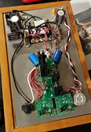
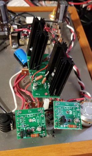
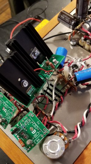
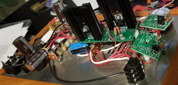
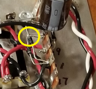
After successfully building my crack and making sure that it worked well, I went to add my speedball upgrade, (older generation), and now the resister not over the transformer but right next to the transformer is putting off a little puff of smoke (at least that what it looks like to me)
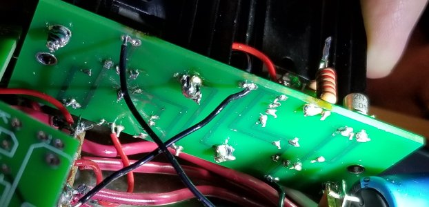
additionally, on the main board of the speedball, I have three LEDs that light up, and the one that doesn't light up is next to one that lights up very bright. the LEDs on the other two speedball boards light up very dimly. One of the LEDs on the nine pin socket also appears to be dim, next to one that lights up bright.
When I first started to measure the voltage, terminal one was perfect while terminal two barley measured at all. I stopped measuring when I noticed the smoke and am worried about getting further measurements. Do you lads have an idea about how I best go about troubleshooting this?
 
It would be helpful to post some pictures of your build. Are your resistance checks coming out ok? You don't need the amp on to check those.
 
You almost certainly haven't properly mounted the TIP50 transistors.  I would go back through the manual and check all those components that are involved in mounting the TIP50 to the heatsink.  Those components function to prevent the metal tab from the TIP50s from touching the heatsinks.  If they touch, then you'll get the issue you're describing.
 
All of my resistors check out with the exception of the one on terminal 12 and 13, is it normal to get sporadic readings on that one? I looked over the tip50, but I don't see that I installed it incorrectly or that the transistor is touching the heatsink. Should I go ahead and reassemble it to be safe? Here are some pictures
 

Attachments

  • 20200123_201324 (2).jpg
    20200123_201324 (2).jpg
    783.4 KB · Views: 13
  • 20200127_154905 (2).jpg
    20200127_154905 (2).jpg
    1 MB · Views: 12
  • 20200127_154957 (2).jpg
    20200127_154957 (2).jpg
    1.2 MB · Views: 8
  • 20200128_141559.jpg
    20200128_141559.jpg
    1,013.9 KB · Views: 5
Don't know whether this could relate to the issue you're having, but I'd double check that the circled diode leads in the  attached pic aren't touching or close to touching. It also looks like there's a lead coming from a diode on the opposite side of the terminal strip that needs trimming.

cheers, Derek
 

Attachments

  • circled.png
    circled.png
    305.1 KB · Views: 20
Can you measure the DC resistance between ground (terminal 12) and OA and OB on the big PC board?

Does the 270 ohm resistor get hot if you run the amp with just the 12AU7 and no 6080?
 
The 270 resistors did not get hot, and 0A and 0B both read .4 on 200v on DCV when the amp was turned off and .8 when turned on (with the 6080 removed). 
 
Can you set your meter to ohms and measure the DC resistance between OA and OB on the big board and ground on the amp?

 
Sorry, it's the old boards (the new ones are labeled slightly differently).  Yes, each "O" pad on the big board to ground would be what I'm looking for.

-PB
 
Okay, I am getting OL on both regardless of how high I set my multimeter to, and I noticed that the heatsink close to the top of speedball gets hot while the other heatsink remains much cooler.
 
Can you post some pictures of the bottom of the large PC board?

Can you also remove the 6080 but leave the 12AU7, then report the I and O voltages on the smaller PC boards?

-PB
 
The image didn't post for some reason, you may want to give it another shot.

That's good news that the small PC boards are working properly.
 
Thanks, that is indeed good news, I suppose the issue is with the main board then. Heres another pic
 

Attachments

  • 20200128_184726 (2).jpg
    20200128_184726 (2).jpg
    606 KB · Views: 13
  • 20200128_184726 (2).jpg
    20200128_184726 (2).jpg
    606 KB · Views: 9
Are you using lead free solder? (sometimes referred to as silver bearing)  How many watts is your soldering iron? 

I see either lead free solder or just not nearly enough heat on those joints.  It does look like some of the pins one or both of the 2N2222 transistors are soldered together.
 
My solder isn't lead free, and I am using an adjustable soldering iron, its wattage ranges from 5 to 60, I probably didn't have it cranked up high enough. I'll redo the solder and message the results.
 
Back
Top