My Crack build w/ manual queries

denti alligator

New member
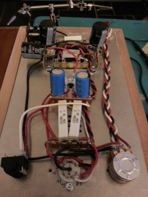
Building my Crack slowly. I'll post the final pic here when I'm done, but I had a couple questions about the manual/build.

One: there are 2  #6 small round lock washers in the kit, but I only see where one was used in the build. Did I miss the other?

Two: on page 13 there appears to be a mix-up of screw lengths being used to secured the two different tube sockets. Just a note for future revisions to the manual. It's pretty clear which screw one is supposed to use.
 
denti alligator said:
One: there are 2  #6 small round lock washers in the kit, but I only see where one was used in the build. Did I miss the other?
Each should go under the #4 nuts that hold down the 9 pin socket.
denti alligator said:
Two: on page 13 there appears to be a mix-up of screw lengths being used to secured the two different tube sockets. Just a note for future revisions to the manual. It's pretty clear which screw one is supposed to use.
That's not a mistake.  If you end up installing the Speedball later, you will wish the long screws in their proper places.
 
I've been following the manual very closely and did not see where the second lock washer was mentioned:

Place the nine pin socket retaining ring over the socket and insert a 4-40  x  3/8”  screw  through the rear mounting hole. 
( ) Hold the screw in the hole while you flip the chassis plate over, and slide a five lug terminal strip over the screw, oriented as shown in the photo. Secure with a #4 nut. Slip another #4-40  x  1/4”  screw  through  the  front  hole.  Slip  a  #6  locknut  on  the  screw from the underside and secure with a #4 nut.

No mention of using a locknut on the first screw.

As to the screw lengths: the language suggests that one is supposed to use the same size screws for each socket:

Octal Socket ( ) Start by putting a #4-40  x  3/8”  screw  into  [...] and insert another #4-40  x  1/4”  screw  in  the  rear  octal 
socket mounting screw hole from the top side. 

[...]

Nine Pin Socket 
[...] insert a 4-40  x  3/8”  screw [...]. Slip another #4-40  x  1/4”  screw  through  the  front  hole. 

So I should use two differently sized screws for each socket?
 
It looks like the instruction for the second lockwasher isn't in the instructions.  You can use it under the nut to hold the 5 lug strip on the 9 pin socket, that's where it should be.

Each socket gets a 4-40 1/4" screw and a 4-40 3/8" screw, they go in the the locations as instructed in the manual.  (You can disregard "another")


Thanks, PB. I will make these changes before moving on. You might want to change "another" to "a" to avoid confusion in future revisions... Though really, that's a nitpicking correction.
 
Everything else seemed to go well enough in the build.

I was wondering why the manual only has one check resistance on some of the terminals, but not all. This is especially odd, because some of the terminals to check have nothing attached to them; yet some that are not listed DO have things attached to them.

Now that I look ahead at the voltage check I see that terminals 18 and 19 are skipped there, too. Any reason?

My resistances were right on, except that terminal 13 appeared to be DROPPING, not climbing. (I just checked this again, and yes, it starts at around 3k and keeps dropping.... I haven't waited to see how far, but definitely below 2.7k.) Is this something to be concerned about?

Also my left RCA measures 87.5k and my right RCA 97.7. Is that something to be concerned about?

Also: the manual says a good place to attach the negative lead of your meter is terminal 12, but there's no ground there). Shouldn't it be terminal 16?
 
Voltage isn't right. See above for resistance inconsistencies. Tubes both glow. Only A8 LED lights up. The A3 one does not.

Voltage issus:

T5: 149

T9: 147.3

A1: 148.6

B4: 148.7

B6: 148

All others are within range. What might I have done wrong?
 
Caucasian Blackplate said:
Do both halves of the 12AU7 glow?

No, it don't think so. Just one. The one closest to the power input/back of plate is glowing; the  one closest to headphone jack/front is not.

I just double checked all the wiring. Seems to be correct. I don't see anything unsoldered. I reflowed and added a bit of solder to A3.

That LED still doesn't light up.
 
Terminal 12 is grounded via the TRS jack that is in turn attached to the ground lug of the potentiometer which is connected to terminal 3 that is the start of the ground.

Here is the ground path of the Crack as described in one of Grainger's posts:

http://bottlehead.com/smf/index.php?topic=4812.0

Richard
 
denti alligator said:
No, it don't think so. Just one. The one closest to the power input/back of plate is glowing; the  one closest to headphone jack/front is not.

That LED won't light up if its half of the 12AU7 isn't glowing.  The red wire to A4/5 provides the heater voltage to make this happen, double check that this connection is well made.
 
denti alligator said:
No, it don't think so. Just one. The one closest to the power input/back of plate is glowing; the  one closest to headphone jack/front is not.

I just double checked all the wiring. Seems to be correct. I don't see anything unsoldered. I reflowed and added a bit of solder to A3.

That LED still doesn't light up.

Have you checked if the LED's are correct in orientation?
 
Don't take my word for this but it sounds like some of your resistors aren't bringing the voltages down to the proper levels. You checked the LED's on the 9 pin miniature socket as well right? That was the one that I missed last time when I had the bands wrong which didn't bring the voltages to the right level. Also, check the fast/soft recovery silicon rectifiers (black/silver banded tiny things) and make sure they are positioned properly.

One last thing, make sure no wires are touching any other wires. This could lead to shorts which will cause your Crack not to work properly.

Posting pictures might help us find the cause of your problem.

 
denti alligator said:
They are. I'll double check the wiring in about an hour when I get home. What do the high voltages at T5, T9, A1,
B4, B6 suggest?

They are all related to the same problem, that one half of the 12AU7 isn't glowing.

If you believe it to be the LED, you can connect a wire between A3 and A8.

-PB
 
Caucasian Blackplate said:
If you believe it to be the LED, you can connect a wire between A3 and A8.

I don't know anything ... I'm at your mercy :)

All I know is what I've posted. Is it possible the LED isn't working? is broken? What will wiring A3 to A8 do?
 
Back
Top