Moreplay Complete: No sound on right channel [resolved]

jminassin

Member
Hi folks,

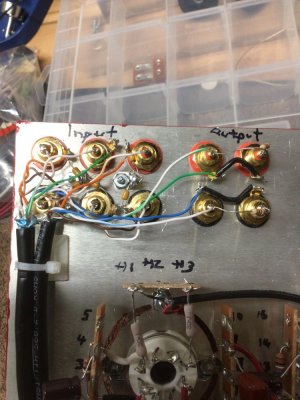
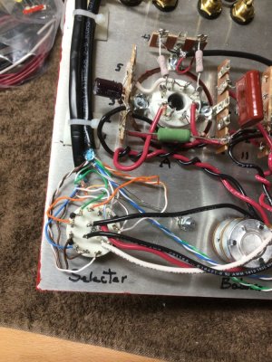
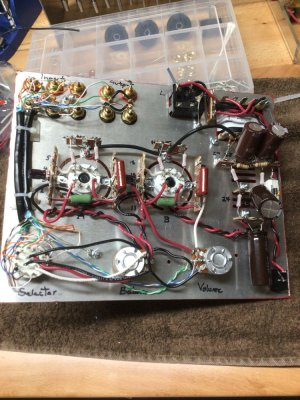
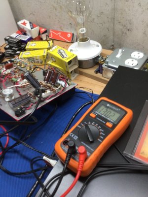
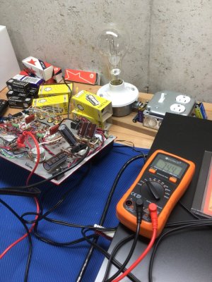
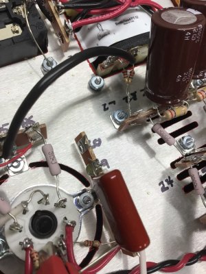
I just completed the first of two Moreplay builds....one for a friend and one for me.  I passed the resistance and voltage tests, and then hooked it up to an amplifier and a CD player.  It sounds awesome, but I have no right channel signal.  I flipped the tubes, but it didn't change anything:  no right channel output.  I shut it down and waited for the caps to drain.  I took a look at the wiring of the RCA jacks and the selector switch, but I can't see anything that looks out of place.

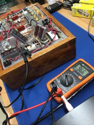
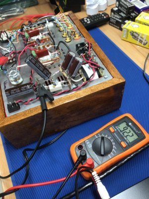
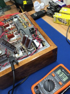
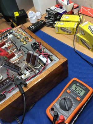
I'd appreciate any input that can help me locate the issue.  I have attached photos.

Many thanks,

John
 

Attachments

  • Moreplay input output jacks.jpg
    Moreplay input output jacks.jpg
    202.3 KB · Views: 26
  • Morelplay selector switch.jpg
    Morelplay selector switch.jpg
    255.6 KB · Views: 29
  • Moreplay full chassis.jpg
    Moreplay full chassis.jpg
    251.4 KB · Views: 34
Start by checking to see if the bad channel works using a different pair of input jacks. If nothing changes try using a different pair of output jacks. Also swap input cables left and right and then output cables left and right. That will help to determine if the problem possibly lies in the input or output wiring or if it might be external to the preamp.

If none of that shakes out the problem you will probably need to use a test tone to trace the signal. Unfortunately I'm having a little issue with optical migraines tonite and can't scrutinize your photos very thoroughly. Perhaps someone else can look them over for you.
 
Ok, I'm using two inexpensive cables to connect a CD player to the input of the Moreplay and the output to an amplifier.  I usually use these cables to test new builds.  I ohmed them out and they test good.  I switched outputs and the left channel signal only plays through both outputs.  If I reverse the left and right output, the signal is reproduced in the right hand speaker as expected.  With regard to the inputs:  I only get the left channel signal through the set of inputs closest to the side of the chassis.  Each of the inputs does the same thing when selected: only the left-hand channel signal is produced.  If I reverse the input wires, the signal appears in the right-hand channel as expected.  Somehow I have lost the right channel signal.

Earlier in the year I built an Akitika Oscillator.  It produces a 1 kH sine wave with distortion of 2 ppm.  I could input the signal into the Moreplay, but I have no idea how to trace the signal.  I know my DMM should be set to AC volts, but I need someone to tell me where to place the probes.  Can somebody help me?

Many thanks,

John
 
You can use an old phone or tablet with an 1/8" to RCA cable playing a 60Hz tone to trace signal, but it would be good to check which meter you have since many of them won't resolve low AC voltages.
 
Paul,  I have a Brymen BM235, but the AC functionality does not work.  My other meter is an inexpensive Neoteck NT8233D PRO.
I have an iPad and I have the oscillator I mentioned.

But my problem is I can't read the schematic.  What points in the circuit do I attach my test leads to?

Does anything look obviously out of place in my photos?

Thanks,

John

 
The Neoteck is fine for the job.

Start by playing a 60Hz tone into the pre with it turned off and the volume up all the way on your source.  Measure the AC voltage at the center lug on each level of the balance pot with the balance pot centered (with the preamp still off).  I would expect an iPad to put out about 0.3V AC, and there is some loss in the balance circuit, so if you see about 0.2V AC on each center lug, that wouldn't be abnormal.
 
Paul,

First I really appreciate your help and patience.  I downloaded a function generator onto my iPad.  I input a 60 Hz tone into the Moreplay.  Moreplay is not powered on.  Volume on iPad is all the way up.  Balance control on Moreplay is centered.

I placed the black lead of the Neoteck on terminal 23 and the red lead on the top middle lug of the balance pot.  I measure approximately 1.3 VAC.  For the bottom middle lug I measure 0.74 VAC.  See pictures.  Does this make sense?

Thanks,

John


Attachments

  • Moreplay Signal Trace Top Lug Balance Control.jpg
    Moreplay Signal Trace Top Lug Balance Control.jpg
    191.6 KB · Views: 14
  • Moreplay Signal Trace Bottom Lug Balance Control.jpg
    Moreplay Signal Trace Bottom Lug Balance Control.jpg
    239.4 KB · Views: 5
Just to clarify, you are feeding the signal into both left and right inputs at the same time?
 
Yes Doc, I am feeding the signal into both channels simultaneously.  The cable has a stereo mini plug on the end going into the iPad and right and left channel RCA plugs going into the Moreplay on the other end.

John
 
Can you unplug the RCA ends from the Moreplay and use your meter to measure the AC voltage between the center pin and shell at each RCA plug?  That seems like abnormally high signal voltage, so it's good to double check.
 
PB,  AC voltage between pin and shell on both left and right channels is approximately 1.3 VAC.  See photos.

Thanks,

John
 

Attachments

  • Right Channel Signal Generator Output.jpg
    Right Channel Signal Generator Output.jpg
    253.9 KB · Views: 4
  • Left Channel Signal Generator Output.jpg
    Left Channel Signal Generator Output.jpg
    244.3 KB · Views: 5
I think what I would do next is to feed your ipad back into the Moreplay with the power off, then set the balance knob so you get approximately equal AC voltage at each center lug. 

I would also check that you have 0V AC on the balance pot where the black wires land.

After you have completed this, now measure the AC voltage at A5 and B5.
 
I'm also not 100% certain that the red wire leaving 9L can do its job.  I would heat up that joint and move the wire so that it touches the terminal strip, then flow some solder between the two.
 
PB,  I crimped the connection of the red wire at 9L and re-soldered.  I used the balance control to have balance at .966 VAC and .922 VAC.  Votage at A5 is .97 VAC and at B5 is .92 VAC.......so the signal is tracking the balance pot closely.

I confirm that I have 0 VAC where the black wires attach to the balance pot.

Thanks,

John
 

Attachments

  • Connection at 9L crimped and resoldered.jpg
    Connection at 9L crimped and resoldered.jpg
    240.8 KB · Views: 9
  • Balance Pot  Voltage Balanced.jpg
    Balance Pot Voltage Balanced.jpg
    228.4 KB · Views: 7
  • Balance Pot Voltage Balanced 2.jpg
    Balance Pot Voltage Balanced 2.jpg
    251.3 KB · Views: 6
  • Voltage at A5.jpg
    Voltage at A5.jpg
    260 KB · Views: 5
  • Voltage at B5.jpg
    Voltage at B5.jpg
    238.5 KB · Views: 8
Is that with the preamp powered up?  With 1V of signal going into each 6V6 socket, we would expect more than 1V to be coming out...
 
Yes Paul, those readings are with the preamp powered on, volume about half way.  Negative lead of DMM is still on solder tab 23.
 
Back
Top