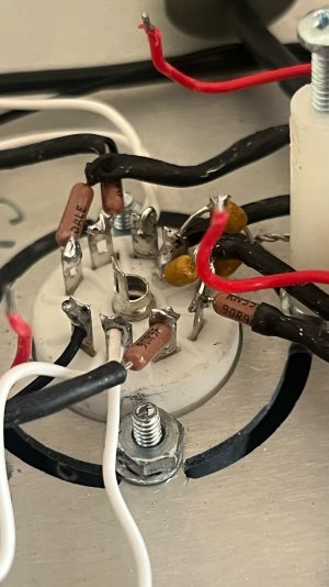
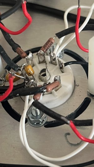
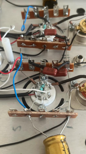
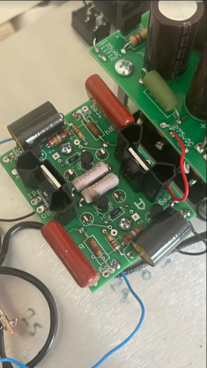
I have just completed an Eros 2 build that did not pass the final voltage checks on the C4S board and the D1/2 D LEDs do not light- going back, the voltages at the MJE5731A on the shunt board are different. Previously at the check point before installing audio circuit, they were both reading 210V, now one MJE5731A (side A) reads 150V while the other reads 210V as before.
IA=IB=270V
OB= Breg side B 210V
OA=Breg side A 150V
Kreg side A = 3.5V
Kreg side B= 7.1V
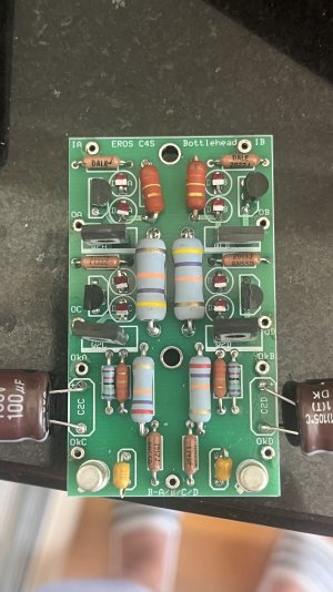
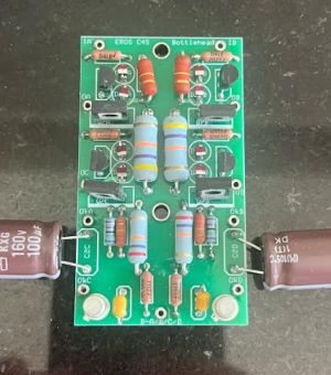
On the C4S board
IA=220V
IB= 150V
OA= 155V
OB= 145V
OC= 95V
OD= 145V
OkA= 95V
OkB= 145V
OkC= 1.4V
OkD= 0.2V
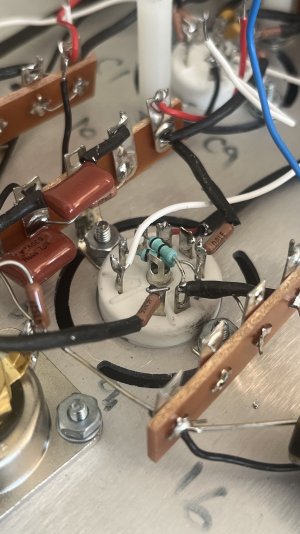
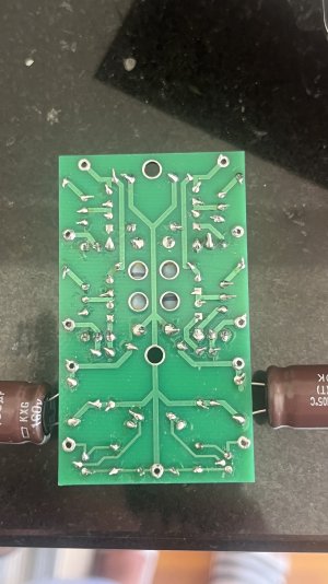
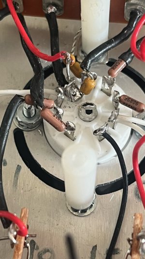
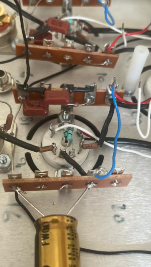
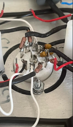
All tubes are lit fine and I tried another set. I have checked the connections on the PCB board and surrounding 12AU7 socket and everything is ok- am wondering which component or area to check next. Am wondering, given the MJE5731A were correct before installing the audio/RIAA circuit and C4S board, if anything there could affect the readings upstream.
Thank you
IA=IB=270V
OB= Breg side B 210V
OA=Breg side A 150V
Kreg side A = 3.5V
Kreg side B= 7.1V
On the C4S board
IA=220V
IB= 150V
OA= 155V
OB= 145V
OC= 95V
OD= 145V
OkA= 95V
OkB= 145V
OkC= 1.4V
OkD= 0.2V
All tubes are lit fine and I tried another set. I have checked the connections on the PCB board and surrounding 12AU7 socket and everything is ok- am wondering which component or area to check next. Am wondering, given the MJE5731A were correct before installing the audio/RIAA circuit and C4S board, if anything there could affect the readings upstream.
Thank you