Missing part?

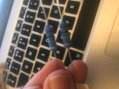
On page 49 of the manual, it says to insert 100k ohm 3k resistors, but I don't seem to have any that look like the picture on the page... is it possible they have been substituted?
If so, to what?!

 
I would recommend getting out your multimeter and measuring the resistance values of the larger resistors in the kit.  They will be substituted with another pair of 100K 3W resistors.
 
From what I can tell, looking at the parts list, these might be the ones!
I'll get the meter on them later
 

Attachments

  • thumbnail_IMG_5418.jpg
    thumbnail_IMG_5418.jpg
    55.3 KB · Views: 15
Yeah, those are the ones.  I recently completed mine with same replacement part, pic attached.
 

Attachments

  • IMG_3078.jpg
    IMG_3078.jpg
    2.5 MB · Views: 20
Chris H said:
Brown, black, yellow, gold is 100k

And here's a chart showing that. It also shows that the gold band indicates +/- 5%.

Brown is 1, black is 0, so that makes 10. Multiplied by yellow, which is 10K, makes 100K.

But I prefer to measure with a meter. Especially with 5% tolerance parts, it can be interesting and informative to find that the values of two "identical" parts are significantly different but within tolerance. Ruling out soldering mistakes, this can explain why the voltages on one channel are slightly higher/lower than the other.  I used to be perplexed by such voltage differences, figuring I had a bad joint somewhere that was adding resistance.

cheers, Derek
 

Attachments

  • 4 Band Resistance_Color Code Chart.jpg
    4 Band Resistance_Color Code Chart.jpg
    75 KB · Views: 6
I can't tell resistor colors apart.  One thing I do is the measure all the resistors in the kit with my DMM and lay them out in order.  Maybe this could help you on future builds.
 
Back
Top