Measuring Resistors In Circuit

Toys4Boys

New member
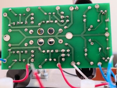
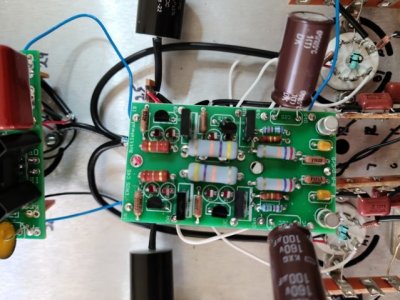
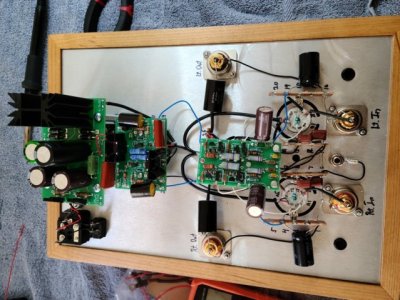
I was foolish enough to solder at extreme temp and apparently cooked some components. I am trying to go back through the parts to see which need to be replaced and have a couple of questions.
1. If a board was completed and voltage tested correctly that would be proof(?) that the components are good?
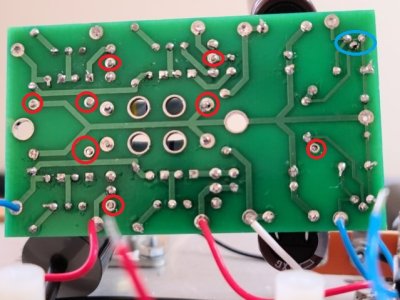
2. When I test various resistors in circuit I get an open circuit, touching he 2 legs of the, I assume that means it is cooked?

Thanks
 
One problem is a cheap multimeter, in the resistance setting some resistors show open, but when I set it to "Auto" mode the same resistor measures fine! Still I believe that I cooked some resistors so the previous questions are still of interest.
 
If it works, the parts are fine.

If you get a good reading automode and open in manual mode you have probably set the meter to too low a manual range for the value of the resistor under test.
 
As components go, resistors are pretty tough. Unless they are visibly discolored they are probably okay...John
 
I'm starting to think the only issue that I had was my multi-tester, oh well a bit late now. One thing that I could use some clarity on is the use of "0 Ohm" resistors?
 
It's a lot easier to use the 0 ohm resistors as jumpers than to strip pieces of teflon coated wire that are cut that short.
 
Well, apparently the problem that I experienced had very little to nothing to do with me, the problem is indeed the piece of c##p
Assark 6000 meter! This caused me quite a lot of consternation and time, in the "Resistance" mode it shows nothing measuring either a 47.5 or 475 ohm resistor, but in "Auto" mode they read as to be expected. I just confirmed this with 4 new resistors sent by Eileen.
 
Back for Vsac 2006, I put together a little amplifier design/building workshop class with PJ, and as part of the class I bought four pocket DVMs from Radio Shack to give to the class participants.  Not a single one of them worked reliably, and I had to run up to the Bottlehead demo room to take all the meters Doc. B had laying around to keep the class going!
 
Doing my voltage checks I'm running into some problems  on the right side of the C4S board, OD measures 140V, OKA 138V, OKC is not reading voltage. The left side is w/in tolerances.
 
What does your meter actually say at OKC?  0V is a valid measurement.  A lot of Eros repairs I get with similar problems just have missed solder joints on that center board.
 
I have gone over the board, soldered any questionable connections, checked for bridges but the right side is still not right:
IA 217V In range
OA 206V A bit high
OC 57V Low
OkA 62 Low
OkC .07V(?)
 
The 0V at OkC may be what's driving all the issues.  Perhaps consider posting some build photos when you get the chance.  Something like this could easily be caused by a solder bridge on the 2N2222 on that side of the PC board, or you could have no heater voltage on the EF86 on that side (the STP that feeds pins 4/5).
 
Huh, don't know why I didn't see your post. I'll take a look tomorrow and send some pics if the suggestions that you made don't resolve the problem.

Thanks
 
I measured pins 4 & 5, 50-56 volts both left and right sides.
 

Attachments

  • 20231108_094441 (FILEminimizer).jpg
    20231108_094441 (FILEminimizer).jpg
    57.6 KB · Views: 10
  • 20231108_094002 (FILEminimizer).jpg
    20231108_094002 (FILEminimizer).jpg
    70.6 KB · Views: 8
  • 20231108_093954 (FILEminimizer).jpg
    20231108_093954 (FILEminimizer).jpg
    82.2 KB · Views: 12
These are the joints I would focus on circled in red, as they don't look well soldered.  In the blue circle, be sure there's no connection between any pair of those pins.
 

Attachments

  • Eros Joints.jpg
    Eros Joints.jpg
    87.8 KB · Views: 22
Back
Top