I have had Jupiter HT caps in my S.E.X. amp for years with no problems. My amp runs almost every day for several hours at a time - 8 hours today. I have had no problems in that time so I dont think you will have heat related problems either. I have a pair of 0.1uF caps in the interstage or coupling position and a pair of 2.0 uF output caps since I have the Magnequest full nickle output transformers installed on my 2.0 version of the amp. I like the Jupitor caps so much I have never wanted to replace them. Although the new copper foil caps are tempting me...
You are using an out of date browser. It may not display this or other websites correctly.
You should upgrade or use an alternative browser.
You should upgrade or use an alternative browser.
Mcandmars ramblings \ build thread...
- Thread starter mcandmar
- Start date
Paul Joppa
Moderator
The original Jupiter caps, in the v2.0 SEX amp (without the ventilation holes in the top plate) has some incidents of melting wax and internal short circuits. I don't think we've heard of any such problems with the new, higher temp versions. Nevertheless, being a conservative engineer, I recommend parts rated 85 degrees C or more. I like my safety margins.
That said, the Jupiters I've heard sound pretty darn good.
That said, the Jupiters I've heard sound pretty darn good.
mcandmar
New member
That's good to know, thanks folks. I also have a pair of 2uf HT's that i was going to install into the S.E.X but decided to keep those for my speaker preamp instead.
Its funny how premium grade capacitors like Mundorfs and Jupiters always seemed a little excessive to me until i actually tried them, now they seem great value")
Its funny how premium grade capacitors like Mundorfs and Jupiters always seemed a little excessive to me until i actually tried them, now they seem great value
mcandmar
New member
Page 21, the paragraph
Just before soldering those two wires i would add in the resistors to C1L, C2L, and C3L, BUT i highly recommend you build the amp completely stock first because if you do have any issues those will only complicate matters and make it harder to troubleshoot. They may also give you different readings for the resistance and voltage checks from what is in the manual.
( ) Using the end stripped back 5/8â€, insert the black
wire into the bottom hole of terminal C1, from the back
side of the strip. Insert the red wire into the bottom hole
of C2. Solder C1L and C2L.
Just before soldering those two wires i would add in the resistors to C1L, C2L, and C3L, BUT i highly recommend you build the amp completely stock first because if you do have any issues those will only complicate matters and make it harder to troubleshoot. They may also give you different readings for the resistance and voltage checks from what is in the manual.
i luvmusic 2
New member
What is the equivalent of the C3X from Hammond(Patrsconnexion)?
Thanks!
Thanks!
i luvmusic 2 said:What is the equivalent of the C3X from Hammond(Patrsconnexion)?
Thanks!
157H is pretty close.
Paul Joppa
Moderator
The current production C-3X may actually be made by Hammond.
i luvmusic 2
New member
THANK YOU!
mcandmar
New member
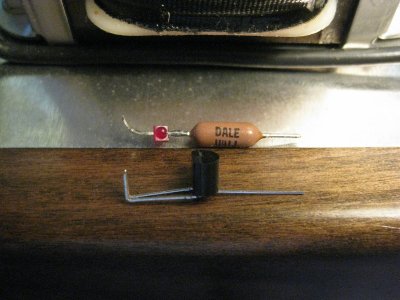
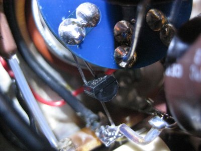
Latest experiment (eXperiment is in the name after all) was to replace the bias resistor in the driver stage with a resistor/LED string. I had a couple of nice precision Dale 499r resistors that i used in the C4S, and a couple of HLMP6000's in stock so there really was no excuse not to try it.
If i worked it out correctly the manual states ~2.5v bias which implys to me the operating point is around 2ma. On that basis a 499r resistor would give a bias of .98v, plus the 1.55v of the HLMP should give ~2.5v combined. In practice i was seeing ~2.2-2.3v before the mod, and approx .2v higher on each side after the mod. Good enough.
Now for the hard bit, does it sound any different? I could convince myself it sounds cleaner and more in focus. But that's probably because that is what i am expecting it to do. Kind of kicking myself i didn't take some frequency response and distortion measurements with RMAA before hand. Either way it cost peanuts, and i dont fancy playing a game of operation trying to get the soldering iron back in there without melting something so they will just have to stay
Grainger49
New member
I feel the same way about a number of minor mods. Taking them out is harder than putting them in. If it didn't harm the sound they stay.
You can use a TL431 or LM431 to get 2.5V of bias, much like an LED. The middle leg goes to ground, and the two outside legs go to the tube's cathode. (The Stereomour uses this)
-PB
-PB
mcandmar
New member
Interesting, i see in the Fairchild datasheet they have a graph for dynamic impedance showing a flat line of .2ohm up past 40Khz. I assume it outperforms the HLMP if you are using it in the higher end kits?
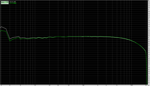
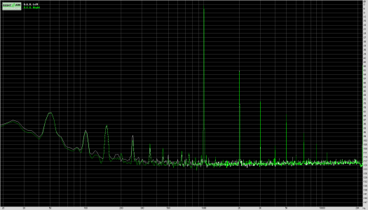
Also have you ever taken any measurements of the S.E.X. amp? I've started using RMAA and i'm not 100% sure of the accuracy of my plots. Its telling me around .3 to .4% THD, but the frequency response seems a little odd, large hump at the very low end and starts to roll off the high end sooner than i expected.
Cheers,
Mark
Attachments
Paul Joppa
Moderator
That looks about right to me - my design target for the output transformer was 40kHz at -3dB, which is -1dB at 20kHz. I can get much better numbers but it would not sound as good for other reasons.
A 1dB peak at 20Hz is reasonable for a parafeed output. It will change depending on the spaeker mpedance - did you load the output with a resistor?
Yes, I'm still on vacation in France, but nursing a cold and bored in the apartment so I'm checking the forum ...
A 1dB peak at 20Hz is reasonable for a parafeed output. It will change depending on the spaeker mpedance - did you load the output with a resistor?
Yes, I'm still on vacation in France, but nursing a cold and bored in the apartment so I'm checking the forum ...
mcandmar
New member
Thats good to know, thanks Paul. The testing was done through a Pete Millett sound card interface so i'm not sure what the input impedance is, i think its around 600ohms. I re ran the tests into 300r and 32r loads and the 32r load does indeed flatten the low end spike, but also doubles the distortion figure. I assume that is to be expected being a more difficult load to drive. The 300r load is pretty much identical to going straight into the interface, which implies the interface is 300r or higher.
I switched out the HLMP/500r string with LM431's as per Paul B's suggestion and the high end frequency response jumped up to pretty much exactly what you specified, -1db at 20khz on the money.
Initially i only changed the left side of the amp and noticed the difference when i compared the left/right channel response. I then changed the right side to an LM431 and the frequency response jumped up there too so its 100% the difference between the two bias setups and not some random change in my testing setup. I'm tempted to solder the stock resistor back in now and measure it out of curiosity
I debated about where to install the 431's as the free positions on the C4S board were very tempting, but in the end the added lengths of wiring from the socket to board swayed me into soldering directly onto the tube socket. Lead lengths were a perfect fit too.
Thanks again guys!
P.S. Get well soon PJ, such a shame to have the sniffles when you are surrounded with nice wines. ...assuming you drink.
Attachments
mcandmar
New member
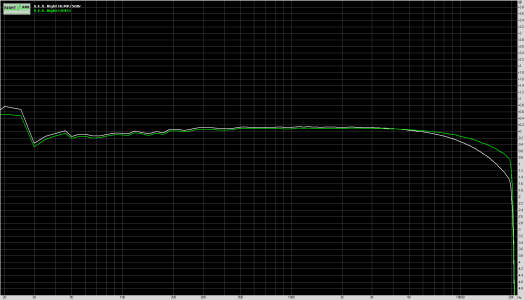
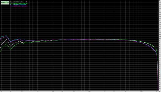
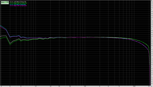
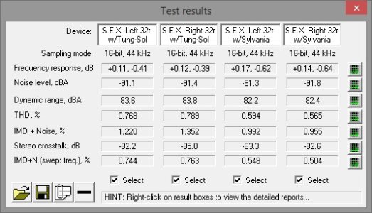
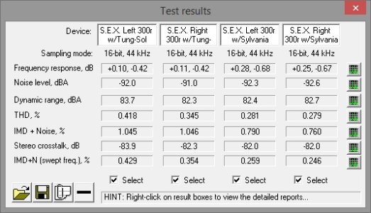
Bonus Content: Tung-Sol vs Sylvania Black Plates
Found this rather interesting, Sylvanias seem to have a slightly flatter low end response, but roll off the high end slightly sooner. They also measure lower distortion figures too. I have attached both 32ohm and 300ohm load plots.
Obviously take all the results with a pinch of salt as results may vary from tube to tube. I dont know how many hours of use the Tung-Sols have, its probably close to six months since i got them. The Sylvanias were fresh out of the box, pretty sure i have never used them. Its still interesting all the same...
Attachments
mcandmar
New member
Found a problem, having just plugged in some headphones i now have a hiss on both channels, i can only assume the LM431's are creating the noise. Have you experienced this Paul, or is there a specific model of the 431 i should be using? Failing that i may have to go back to the LED/Resistor string.
Cheers,
Mark
Cheers,
Mark
Similar threads
- Replies
- 3
- Views
- 2K