Mcandmars ramblings \ build thread...

Paul Joppa said:
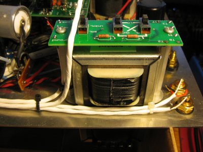
In the SEX 2.1 (with PT-7 power transformer) the heater power is only connected to ground for two short periods during the 60Hz power line cycle - just when the diodes are conducting. Most of the time it floats. For that reason, if there is a little leakage between heater and cathode, the voltage will drift away from symmetrical. You can put a couple 100-ohm resistors in series across the DC power and ground the center point if you want to see matched voltages; you are not however going to hear a difference unless the leakage is so bad the tube should be replaced.

The center tap is grounded so that the winding itself is always grounded. This allows it to act as an electrostatic shield for other windings.

This little tip is worth adding to the thread, adding 100ohms resistors from C1&C2 to C3 creating a grounded center point helped to further reduce the harsh bzzzt noise i was hearing, and also allowed me to use sets of tubes i had previously written off as being too noisy.  In my opinion this simple modification made such an effect i would suggest trying it first before experimenting with other modifications, or fitting the 120ohm resistors to the headphone socket.  As always, please report your findings if you do try it...
 
Have you found the source of the buzz?  If you are as handy with a scope as you with assembly you could find if it is of power supply or signal path origin.
 
Not really no. Its not in the audio path so its either HV supply, or heater supply. I had ruled out the heater supply as doubling the capacitance of the filter cap to 22000uf halved the ripple and made zero difference to the output noise.  Having said that the above experiment creating a grounded center point on the DC side of the heater supply did make a difference so i'm not really sure what that tells us.

I cant measure the HV supply directly as my scope is limited to 400v peak to peak. I tried modeling the supply in PSUDII and experimented with difference capacitance and got some very odd results, for example doubling the first two 220uf caps to 470uf actually made the ripple worse at the end of the chain.  However when i replaced the two 680ohm resistors with chokes it did reduce the output noise so i'm almost certain it is coming out of the HV supply.  How to improve it further i just dont know, or maybe this is just the limit of the capability for these tubes.

The caps themselves are as good as it gets for their value and rating, i haven't found anything better than those Panasonics.  I do have two 22uf Panasonics to try at the end of the chain to replace the Lelons as they have better specs, but i dont expect much if any difference. I also have a couple of 2.2uf film caps to try bypassing those but without a way to measure/quantify any difference i am going to hold off.

At the moment i have the noise floor below what is audible so i am perfectly happy with it.  But if i could get it to the stage where i could do without the two 120r resistors in the output path that would be even better as i dont like the high end roll off they caused.  Or maybe i just need to try another brand of resistors.  The real problem is the sensitivity of my headphones, HD650's without the 120r resistors its barely audible, but with the Grados i need the resistors to hide it.
 
You can make an L-pad, combining the series 120 ohm resistor with another resistor from headphone tab to ground. This reduces the signal level just the same but presents a lower impedance to the headphone. Try 47 ohms series and 22 ohms in parallel with the headphone - that will give the same attenuation as the 120 ohm resistor (assuming 32 ohm phones) but  a source impedance of 15 ohms instead of 120 ohms.
 
Interesting, i will give that a try.

I was thinking about what resistors to order and realized i never actually tried the amp without the 120r resistors since i installed the 100r resistors into the heater supply. As a test i made up a quick adapter cable from the XLR socket to a TRS socket to bypass them and found its perfectly fine. I had to power down my PC to reduce the ambient noise and really listen to detect any background noise with the Grados, result!

Since i had the cable made up i started switching between the TRS socket (with 120r's) and the XLR without and sure enough the SQ between them is very different. There was a good 1/4 turn of the volume knob between them making absolute a/b comparisons difficult but the conclusion i came to was the resistors make it sound what i would call more tubey. The sound had a softer, rounder edge to it and was much smoother sounding overall.  Without the resistors there is a step forward in clarity and detail, and a proper sharp attack/decay to snare drums and percussion, less of the woolliness basically.

Funny thing is i like them equally as they both have their pros and cons. I'm going to use the adapter cable for a while and see which i prefer over time before i jump in and remove them permanently.

I also rolled a few other tubes into the amp and confirmed the amp was quite with multiple sets so those 100r's really do make a big difference.
 
Stepped Attenuator:

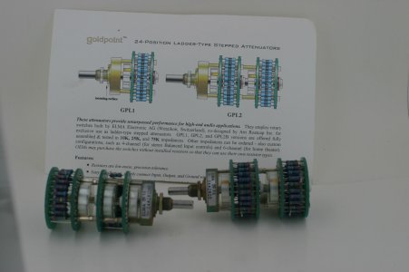
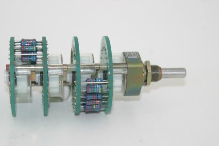
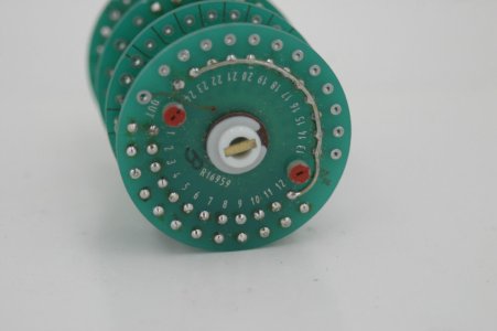
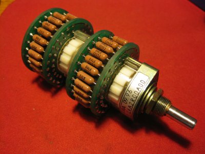
I recently got my hands on a vintage Goldpoint ladder attenuator and matching balance control from eBay. The switches are dated Sept 1996 and have never been used.  They are 75k items however since i have no need for a balance control i am going to rebuild it into a 100k attenuator for use in the S.E.X. amp.

Since the ladder version of the Goldpoint has been out of production for so long i did a bit of digging around in the internet archives and found a copy of the website from early 2000 with the assembly instructions.  I have attached the list of resistor values from the Goldpoint site along side the values used in the Chinese attenuator i am currently using.  I do prefer the look of the curves on the Goldpoint item, smoother looking and starts to raise the volume sooner than the Chinese version.  Also the switch feel is much more pleasant on the Goldpoint.  As soon as the resistors arrive from Mouser i will assemble and add some more pics.

If anybody knows what resistors were originally used in these i would love to know, they all have six colour codes which i had never seen before, which translates to 1% 50ppm.

index.php
 

Attachments

  • GoldPoint.JPG
    GoldPoint.JPG
    160.7 KB · Views: 291
mcandmar said:
They are 75k items however since i have no need for a balance control i am going to rebuild it into a 100k attenuator for use in the S.E.X. amp.

The 75K control will work quite well in the SEX amp, there's no need to rebuild them.
 
I feel the need to warn you:

I am not aware of the Goldpoint balance control.  But I have worked with balance controls that are continuous. 

A balance control attenuates the left channel and leaves the right channel alone when you fade to the right channel.  It does the opposite when fading to the left channel.  The operation of leaving one channel alone is unusual for a dual channel device.

If Goldpoint made a switch specifically for balance it will have no positions for the two channels either side of centered. 

If Goldpoint used a standard switch and just shorts all the positions either side of center you will be able to make a stereo attenuator from it.
 
Caucasian Blackplate said:
The 75K control will work quite well in the SEX amp, there's no need to rebuild them.

Thanks Paul, that is what i was querying the other day.  The 75k attenuator i will leave as is, its only the balance control i am going to rebuild back into a volume attenuator.  The dilemma i have is which will be better, the rebuilt one using modern Vishay Dale RM/CMF55's, or the original one which i think has "1%, 1/2 watt, Xicon, 50ppm, metal film" resistors.

Grainger49 said:

If Goldpoint used a standard switch and just shorts all the positions either side of center you will be able to make a stereo attenuator from it.

Thanks for the heads up Grainger, that is exactly what it is, the same physical switch unit with half the resistor positions joined together.
 

Attachments

  • balance.JPG
    balance.JPG
    121 KB · Views: 201
  • balance2.JPG
    balance2.JPG
    122.5 KB · Views: 202
So you know that feeling when you hunt down a pair of nice tubes for a bargain price. That was me on Friday evening with a beer in hand unpacking a NOS pair of Sylvania Black Plates, my favorite.

These tubes turned out to be a rather unique variety i have never seen before, they have the Sylvania skinny black plate primary, but with the regular GE/RCA grey plate secondary inside a coin base package.  Also the labeling on the tubes is green which i have never seen before, they are always yellow. I was really curious to hear what these oddballs sounded like.

They initially powered up fine, plugged the headphones in and had a static noise on the left channel.  Hmm, tap tap, bbbzzzzzZZZZtt POP fzzzztt, and with that the heater went out and the other tube dimmed and the pilot light started flickering. I somehow managed to flick the power switch off and rip the headphones off my head without spilling the beer all over the place. Deaf in one ear and with a heart rate through the roof no less.

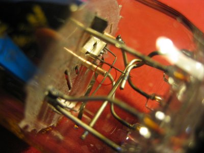
After i regained my composure and burnt my fingers on the tube (i do that every time), i swapped them around and powered up again without the headphones.  One dead tube, and obviously still shorting out the heater supply. On closer inspection i found the issue is one of the grid support rods is making contact with the heater element, incredibly frustrating i cant get in there to do anything about it.  I may have to introduce this tube to Mr Hammer and Dr Dissection in the name of science.

Thankfully the fault seem to be on the secondary side so it didn't introduce the DAC to a heater supply, and the headphones survived the ordeal too.  Only permanent damage is to my hearing and nerves.  I have a new rule: Always use sacrificial headphones when tube rolling, and be ready for a surprise!
 

Attachments

  • heater.JPG
    heater.JPG
    619.2 KB · Views: 282
I think your new rule is prudent. My scare, documented in another thread, caused by transistor failure in the C4S board will require me to follow your rule and use a pair of cheap speakers for a few hours after I reinstall the board.
 
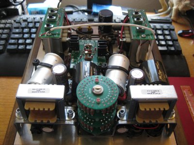
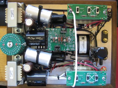
What better way to spend a friday night than waving a soldering iron about, sad b£&*$@% that i am.  I finished rebuilding the vintage Goldpoint attenuator a while back and never got around to fitting it so i had a look through my parts stash at the bits and pieces i have gathered up and figured i would throw them all in at once.

While i was switching out the attenuator i took the opportunity to replace the last of the audio path wiring from the RCA inputs to attenuator, and the short length from there to the standoffs with dual core silver plated shielded wire sourced from Navships on eBay. I've always liked his stuff, nice quality and really cheap.

Other misc bits thrown in include two new RCA input jacks, two .1% 25ppm Dale 1/2w resistors for the power supply, two Panasonic 22uf caps to replace the Lelons, and as an experiment i added two .22uf Mundorf bypass caps across them to see what happens.  I did a similar experiment with my "Babybottle" quickie and was really surprised at the effect they had.

Conclusion?  The Goldpoint is just lovely, instead of the clunk clunk clunk of the eBay attenuator it goes tick-a-tick-a-tick-a-tick, its just sexy.  The amp also sounds different, seems much clearer with better detail in high frequencys.  Then again after four cans of Heineken a speaker in a metal dust bin would sound good to me ;D
 

Attachments

  • atten.JPG
    atten.JPG
    774.7 KB · Views: 202
  • cable.JPG
    cable.JPG
    683.3 KB · Views: 209
  • IMG_6993.JPG
    IMG_6993.JPG
    716.5 KB · Views: 212
  • IMG_6961.JPG
    IMG_6961.JPG
    849.9 KB · Views: 301
(Tung-Sol 6DN7's)

I managed to score a pack of five NOS Tung-Sol tubes which i have been looking for since i bought this amp, they are by far the rarest of all the 6DN7 tubes.  I blame Doc for this due to his comment about them sounding a bit different on the forum :P

The construction and plates are a little bit different to regular GE/RCA tubes, the first sections have black plates, the second sections have grey plates, and they have a D shape getter mounted on the side of the first section which is unique.  Every other tube i have seen has had an O ring getter behind the second section.

First thing i did was plug into into my tester and measure the output, results were a bit all over the place, for five NOS tubes from the same batch i was expecting a bit more consistency.  I also noticed they all measure close to the rated 40ma for the second section as per the datasheet, where as most of my Sylvanias measure higher in the 50ma range which is interesting, and has me wondering if this contributes towards my preference for them having a slightly stronger output.

So how do they sound?  They have less of the midrange tubyness the Sylvanias have, or if you like they are a little less euphoric.  Low end is similar, possibly more extended, but cleaner and better defined. The high end is also clearer and more extended then the Sylvanias. Overall i think they are a more balanced sounding tube vs the Sylvanias that seem to emphasize the midrange more.  There is some other quality to the Tung-Sol's i haven't been able to pin point yet, they just sound a bit different, but in a good way.

As with all the 6DN7 varietys were not talking a night & day difference, its more subtle to the extent it takes a pair of headphones and some careful listening to pin down the differences.  Having said that i would confidently take the Pepsi challenge on GE/RCA vs a pair of Sylvanias or Tung-Sols, the difference is enough to be able to single them out, and enough to make them worth seeking out.

index.php
 
I agree with you, the Tung Sol's sound good but very similar to everything else out there.  My pair was a gift from a fellow Bottlehead and I leave them in not out of their sound but to honor the gift.  The 6DN7 lasts forever in this amp!
 
I've started my build and am following recommendations here - nice build by the way!

Is there a range that is acceptable to the 100r Resistors to be put in the heater circuit?  I've got quite the pile of resistors but none (other than some monster 12w Mills that are not going to fit) that are 100r.  Recommeded wattage range?

Thanks!
 
Good question, and i don't really know the answer as that as the value was recommended by PJ.

From what i understand using lower value resistors will center the voltages more accurately, but at the expense of using more current and dissipating more heat.  I dont know how to calculate the current across the resistors, and therefore the wattage rating needed so hopefully one of the BH guys will chime in and educate us...
 
Ohms law works pretty well.

6.3V with 200 Ohms across it.

P=(V^2)/R

To keep temperature reasonable, triple that power to get your resistor wattage rating.
 
See, you always make it sound so simple :)

In that case i get a little under .2w with 100r's so a quarter watt resistor isn't going to cut it, unless you jump upto 200r's in which case your down to ~.1watt. Got it.

Thanks Paul!
 
Caucasian Blackplate said:
To keep temperature reasonable, triple that power to get your resistor wattage rating.

mcandmar said:
In that case i get a little under .2w with 100r's so a quarter watt resistor isn't going to cut it, unless you jump upto 200r's in which case your down to ~.1watt. Got it.

.2W of dissipation means 1/2 Watt minimum resistor size, but more likely a 1W part.
 
Thanks gents!  'preciate the info.  I can sling solder around with the best of 'em but my electronic knowledge is on the level of what a dog knows about brain surgery. 
 
Back
Top