Mainline switches [resolved]

bergurbrag

New member
Dear Mr. Birkeland,

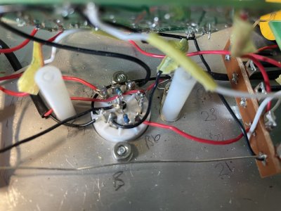
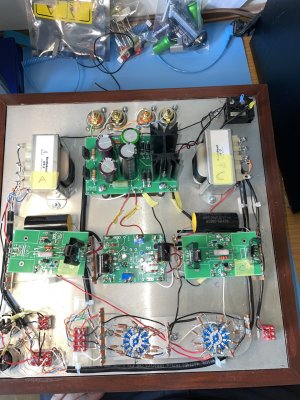
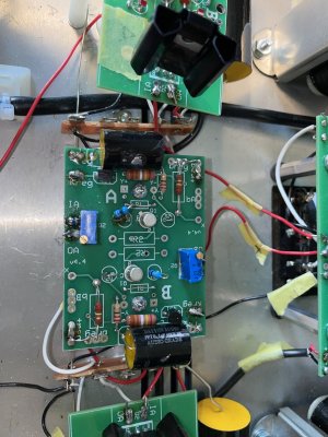
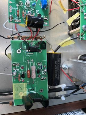
I have run into some issues with my Bottlehead Mainline amp. I discovered a short circuit and it seems it has possibly damaged some parts. I have since then fixed the short circuit.
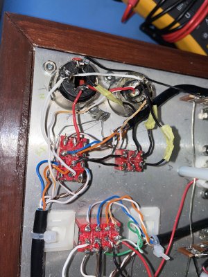
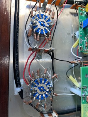
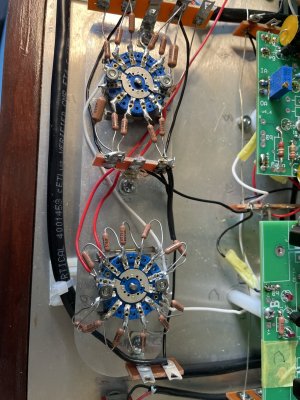
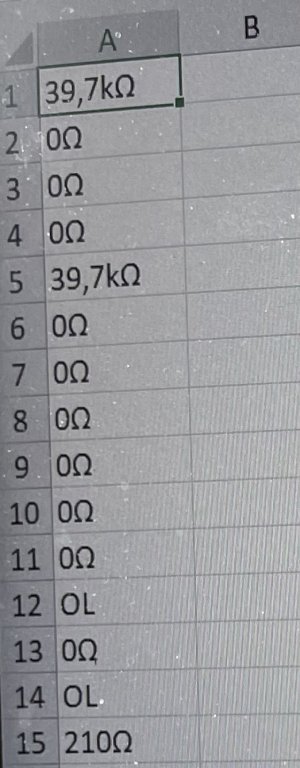
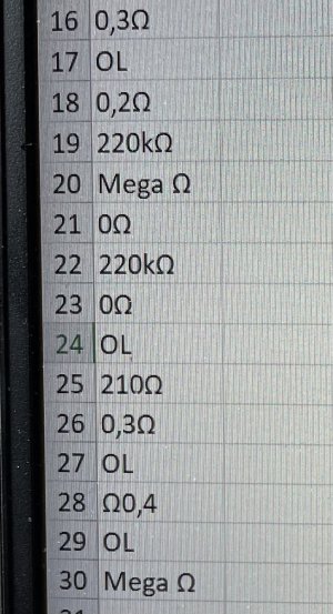
Two 48,7 k ohm resistors connected between 2U and terminal 8 on the fin attenuator switch and 8U and terminal 2 on the fine attenuator switch are shorted. Also the output and impedance switches have a continuation (the multimeter beeps continuously) between all pins regardless on how the switches are positioned. I have not tried to desolder the switches.
The input switch seems to be working correctly the continuation changes when I flip the switch, only pins 5 and 8 stay the same as far as I can see.

Does this indicate that the output and impedance switches are toast and the input switch is ok ?

I might have some other questions but this will do for now.

With Regards,

Bergur Bragason
 
The impedance switch is connected to the secondary winding of the output transformers, so all the terminals are likely to read very low resistance to each other unless you disconnect the wires.  For what it's worth, I cannot ever remember anyone having one of those switches fail.

The 48.7K resistors likewise are extremely unlikely to short out.  There may be something else at work that's causing what you're measuring, so I would post some build photos before attempting to remove them.
 
Hi !

Thank you for your instant answer, I appreciate that !

I have desoldered the output switch and measured it. It seems to be working fine. Maybe you can confirm that ?
When in the first position there is continuity between 1 and 3.  2 and 4. In the other position between 3 and 5. 4 and 6.

If I understood you correctly  the impedance switch has continuity because it is connected to the output transformer. I really do not want to desolder it because there are so many leads going to it.

Regarding the resistors I have measured all the resistors connected to the fine and course switches and all are working fine apart form those I mentioned. I have to Fluke multimeters and both read the same....

With regards,

Bergur Bragason
 
I merged your second thread with the thread you already started.  Please just reply to this one instead of starting new ones. 

Yes, as I said before you should see continuity between pretty much every switch lug on the impedance switch.  If you take apart every part of the amp that you believe isn't working properly, you're likely to do more damage and create new problems that aren't there currently.  This is especially true in the volume control section, as it would be likely that you'll damage the switch trying to remove the 48.7K resistors, when ultimately there is something else likely to be at work.  This is why posting some build photos would be very useful.

These resistors don't just fail as a dead short, so we will really need to inspect what's built to attempt to help you resolve this issue.

 
Ok, thank you very much !

I am waiting to receive a transistor that got damaged. I will do a resistance and voltage check after I install it and then come back to you with some questions and photos if needed.

Can I use this thread ?

Bergur
 
Hi !

Here are some build photos.

Please tell me if you can spot any issues
 

Attachments

  • IMG_8955.jpg
    IMG_8955.jpg
    474.9 KB · Views: 5
  • IMG_8957.jpg
    IMG_8957.jpg
    529.1 KB · Views: 4
  • IMG_8958.jpg
    IMG_8958.jpg
    460.9 KB · Views: 3
More photos
 

Attachments

  • IMG_8963.jpg
    IMG_8963.jpg
    579.5 KB · Views: 1
  • IMG_8962.jpg
    IMG_8962.jpg
    680.8 KB · Views: 5
  • IMG_8961.jpg
    IMG_8961.jpg
    613.3 KB · Views: 6
  • IMG_8960.jpg
    IMG_8960.jpg
    585.4 KB · Views: 6
  • IMG_8959.jpg
    IMG_8959.jpg
    481.2 KB · Views: 4
and more photos
 

Attachments

  • IMG_8969.jpg
    IMG_8969.jpg
    652.5 KB · Views: 8
  • IMG_8968.jpg
    IMG_8968.jpg
    506 KB · Views: 3
  • IMG_8967.jpg
    IMG_8967.jpg
    510.6 KB · Views: 5
  • IMG_8966.jpg
    IMG_8966.jpg
    506.3 KB · Views: 2
  • IMG_8965.jpg
    IMG_8965.jpg
    476.8 KB · Views: 5
  • IMG_8964.jpg
    IMG_8964.jpg
    567 KB · Views: 3
  • IMG_8963.jpg
    IMG_8963.jpg
    579.5 KB · Views: 4
Thank you for your advice. I have some micro cutters witch I will use.

I will come back soon with some resistance and voltage measurements
 
Hi !

I appreciate your help very much.

Apart from trimming the leads did you spot any failures, any wrong connections, missing connections etc ?

 
Dear Mr. Birkeland,

I am sending you photos of an Excel document with my resistance measurements

At first glance you may spot some OL readings. Those are to unconnected terminals witch, according to the manual, should be unconnected. There are 6 of those. Terminals 12, 14, 17, 24, 27, 29.

Those with specific numbers written in the manual are all ok. There are a few who are 0,3 Ohms where there should be 0 Ohms.

Terminals 19 and 22 have an * in the manual and those have a reading of 220k-Ohms.
Terminals 20 and 30 had a reading of some Mega Ohms.

Are these measurements correct and is it OK to proceed to voltage test.

Please give me a feedback

With Regards,

Bergur Bragason
 

Attachments

  • IMG_8971.jpg
    IMG_8971.jpg
    178 KB · Views: 2
  • IMG_8972.jpg
    IMG_8972.jpg
    567.2 KB · Views: 3
Hi !
I am a little bit worried when it comes to the voltage check. The Amp works well but to get high enough output I need to turn up the input signal almost to the top.

I have done the biasing and it is 145VDC on both sides. The rest is as follows:

+275vDC on the Power Supply Board 275V      269VDC
+6.3vDC on the Power Supply Board 55-65V  59VDC
-6.3vDC on the Power Supply Board 50-60V  52VDC
IA on the A side C4S Board                 275V      270VDC
IA on the B side C4S Board                 275V      270VDC
Breg Regulator Board (both sides) 220V      215VDC
-reg Regulator Board (both sides) 0V          0VDC
Kreg Regulator Board (both sides) 8-12V    9VDC

Seem all ok but the input voltages to the PSB are 8,5VAC and 117,6VAC under load. I measured these secondary windings voltages as 135VAC and 9VAC before soldering them to the PSB. I used stranded wires of the same diameter as those solid ones that came with the kit.

Is this problematic ?

With Regards,

Bergur
 
Using stranded wire in a kit is a really, really bad idea.  It's not a problem to have the level controls turned up almost to the maximum; that is relatively normal for certain headphones when paired with the Mainline.
 
Ok, thank you for your answer. This is the only place I used stranded wire in the whole build.

I have some wire left, one that is not stranded, black and red and a drain wire in a black sheathing. The same that is soldered to to 6,3VDC terminals of the PSB.

Is it ok to use that wire ? I will off course trim off the drain wire.

Is the reading of 117,9 VAC and 8,5VAC ok under load ?
Are the other readings ok ?

Bergur
 
... I have measured the wire I would like to use and it is a hair larger in diameter both striped. I am talking about the one with a drain wire and a foil shielding.

Please advice me on this matter
 
Back
Top