Tabaia said:can you provide some constructive feedback please
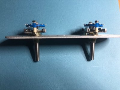
Paul Birkeland said:The 1N5820s and the 5W resistor have not been heated enough to be properly soldered.
Tabaia said:can you provide some constructive feedback please
Paul Birkeland said:The 1N5820s and the 5W resistor have not been heated enough to be properly soldered.
We use essential cookies to make this site work, and optional cookies to enhance your experience.
")