Loud Pop In Right Channel Followed By No Sound [resolved]

Hi Paul,

So I was able to use another GE 6080 tube in my amplifier. I did this to have a control in order to rule out either a bad tube or if there is something wrong with the amp that I assembled. The new 6080 tube that I put in was used and it also tested well on a tube tester so I knew beforehand there was nothing wrong with it. Upon powering the system on there was the same blue glow with a bright flash from the 6080 tube. I believe this rules out a bad tube, and I think I should direct my attention to the amp. Also, LEDs still turn on.

I went ahead and did my resistance and voltage checks again:

T1 = 3.65 M ohms, 77.2 V
T2 = 2.65 M ohms, 177.2 V
T3 = 0 ohms, 0 V
T4 = 2.15 M ohms, 177.4 V
T5 = 2.07 M ohms, 80.6 V
T6 = 0 ohms, 0 V
T7 = 2.92 K ohms, 102.9 V
T8 = 0 ohms, 0 V
T9 = 2.95 K ohms, 107.1 V
T10 = 0 ohms, 0 V
T12 = 0 ohms
T13 = 4.33 M ohms
T14 = 0 ohms
T20 = 0 ohms
T22 = 0 ohms
B3 = 2.98 K ohms
B6 = 2.98 K ohms
RCA Jacks
Center Pin  L = 95.3 K ohms, R = 94.5 K ohms
Ground Tab L = 0 ohms, R = 0 ohms

Let me know what you think I should try. Thank you again for your help!
 
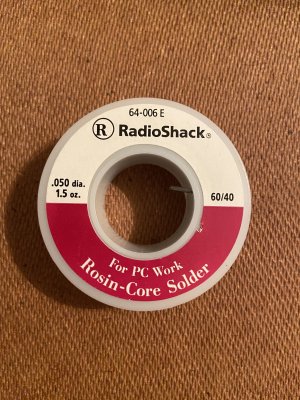
I attached a pic of the solder that I used during assembly. It says that it is 60/40 rosin-core solder for PC work. I made sure to get this kind because that was what was recommended in the manual. I did not use any extra flux during my assembly.
 

Attachments

  • 60_40_solder.jpg
    60_40_solder.jpg
    3.1 MB · Views: 11
Likely won't fix things, but it's easy and worth a shot: take the chassis out of the base and hold it at lots different angles while shaking/banging it (without tubes) to clear any stray lead clippings that might be lodged somewhere they shouldn't be. They can end up anywhere. When I rebuilt one of my amps, I found a bunch of lead clippings in the power transformer end bell.

If that doesn't work, you're best bet is probably to reflow every joint - including the hard to reach ones. What almost everyone does (i've been guilty of same) is reflow only the ones that are easy to get at.

cheers and good luck, Derek
 
Hi Derek,

Did the shaking, but nothing came out or loose. The only solder joint that I have not reflowed is 3L. I cannot really see it very well or get to it. Trying to figure out how to do it. I appreciate the help!
 
I'm glad to see that you used the recommended solder and no extra flux.  You could definitely create the problem that you're having by using the wrong soldering projects. 

I would get a wooden chopstick and run the amp with a cheap pair of headphones plugged in, then poke around the circuit until you actuate the pop.  That will help you focus your efforts on what's loose.
 
Thanks PB! I will look around for a cheap pair of cans. I may have to go out and get a pair that I don't mind potentially breaking. For clarification, I turn the system on with tubes connected and poke each soldered joint with a chopstick until I hear something unusual from the headphones? Also, should I be playing music or play nothing and only listen for a pop/noise?
 
I appreciate your help! May be a couple of days before I post back. Any recommendations on a cheap pair of cans that comes with a 1/4" adapter?
 
I appreciate it! I went ahead and ordered the second option (Maxwell + 1/4" adapters). I'll grab some takeout and get an extra pair of chopsticks while I'm out later haha.
 
I thought of another question to ask. How important is it to crimp the wires around joints? I originally did not do that very well. I have gone back to crimp as many as I could and then applied more solder to the joint. There are still some areas where this could be done.
 
Crimping on the wires is made much easier with suitable miniature pliers of various types. Pay a little extra for better made items. Many wires can be pre bent with fine pointed needle nose pliers before insertion. The hook then allows the wire to be squeezed a bit before soldering. Cut off the excess as you go. Having good and suitable tools for this work makes it more satisfying. Tool junkies know the feeling.  :)
 
Yes, having a good pair of needle-nose pliers is game changing haha. About halfway through my assembly I went out and got a good pair. No way would I have been able to assemble the kit without them.

I will be conducting my chopstick test later today. The only area that most likely needs to be re-soldered is 3L, but I have no idea how to get to it.
 
Hi Paul,

Just performed the chopstick test and I did not hear any pops or noises come from the headphones. I verified the Maxwell headphones worked by plugging them into my solid-state amp and briefly playing music through them.

I had the headphones off my head during the test but held them close to an ear. I did this because I wasn't sure how loud a pop or noise would be. I also had the volume slightly turned up. Want me to crank the volume and perform the test again?

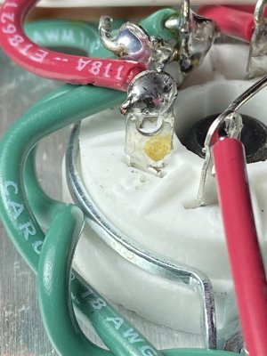
When I was inspecting all of my joints I found that pin 6 on the 8 pin is slightly broken/cracked at the base. Could this be causing my tube to arc or whatever it is doing at the startup? Could I just run some solder over it to "fill it in"? My resistances and voltages are passing each time I perform tests (I run through the checks prior to powering the system on every time).

Also, my 3L terminal looks good on soldering.


Attachments

  • pin_6_on_8pin.jpg
    pin_6_on_8pin.jpg
    1.2 MB · Views: 16
The socket contacts are twisted in order to hold them in place, so there's nothing wrong there.  Are you 100% certain you poked at all the joints?  You could do this with the volume all the way up, there's no harm in trying that.
 
Back
Top