kill_surf_city
New member
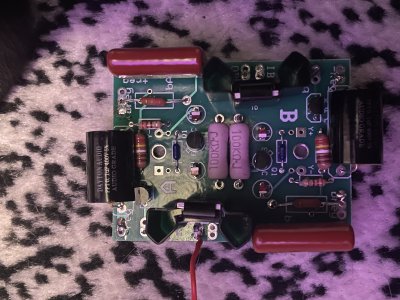
Paul Birkeland said:The next thing to do would be to set your meter to beep when you touch the probes, then start probing all the pairs of all the transistors and the 431 regulators on the board above the D socket to see if any of them are internally shorted.
Both of the 100KΩ 3W are beeping on opposing ends. Also one end of each of the 0.1 μF 400V film capacitors, the 431 resistors on side B and A as well as the 2.49KΩ resistors