left channel suddenly out of balance [resolved]

kill_surf_city

New member
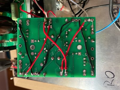
I just finished my build with SUTs installed and i rechecked the voltages and everything was good. I had a very low hum in both channels, but that may or may not be an issue with my main amp. I did some check of cords and such, then when i turned the amp back on, the left channel was out - well turns out it's just out of balance. I'm getting sound out of it but the right side is MUCH louder. My LEDs are still coming on but I see the ones on the top of the C4S board near IB aren't quite as bright. I measured voltages

IA - 215v
IB - 118.8v

OA -158.4v
OB - 115.4v

OC - 97.1v
OD - 98.1v

OkA - 98.1v
OkB - 97.9v

OkC - 1.235v
OkD - 1.523v

Where should I look for a problem?
 
I would disconnect the blue wires feeding the "I" terminals on the front C4S board and redo the voltage checks on the C4S shunt regulator board above the 12AU7 socket.
 
Paul Birkeland said:
I would disconnect the blue wires feeding the "I" terminals on the front C4S board and redo the voltage checks on the C4S shunt regulator board above the 12AU7 socket.

Okay side B is reading as 216v

side A of the board is reading 188.5v

any specific joints i should check?
 
damn it. i was doing some probing to try and find the source of the issue, and something sparked on one of the 100kohmJ parts and now two of the LEDs on the A side are out.....but I am getting 249v on the side that was lower. Not sure what to do now.
 
Post IA, IB, OA, OB, KregA, KregB voltages.  There was and still is something wrong with the power supply regulator that's built on the 12AU7 socket (which I why we have you test it early in the build), so this portion of the circuit needs to be working properly before moving along to the rest.
 
Paul Birkeland said:
Post IA, IB, OA, OB, KregA, KregB voltages.  There was and still is something wrong with the power supply regulator that's built on the 12AU7 socket (which I why we have you test it early in the build), so this portion of the circuit needs to be working properly before moving along to the rest.

IA - 256v

IB - 253v

OA - 250v

OB - 217v

KregA - 183.6v (this value never seems to pick a number, it floats around this range

KregB - 1.95v
 
Something like this could be a shorted 431 regulator, though typically we don't see them short in that manner, or possibly a jumper on the C4S board above that socket that isn't wired properly.
 
Paul Birkeland said:
Something like this could be a shorted 431 regulator, though typically we don't see them short in that manner, or possibly a jumper on the C4S board above that socket that isn't wired properly.

Sorry, I don't understand. The C4S board was disconnected from the IA/IB leads when I ran this  test. Which one is regulator is 431?
 
Paul Birkeland said:
Something like this could be a shorted 431 regulator, though typically we don't see them short in that manner, or possibly a jumper on the C4S board above that socket that isn't wired properly.

here's the underside.
 

Attachments

  • board.jpg
    board.jpg
    944.1 KB · Views: 10
There's a front C4S board that sits up by the three signal tube sockets, then a C4S regulator board above the D socket.  On the C4S regulator board you've shown me, I would reflow all the solder joints other than those for the LEDs.  If you are using lead free solder, I would grab some 60/40 Kester rosin core solder.  If you are using leaded solder, I would turn up the heat so things are a bit more willing to flow out.
 
Paul Birkeland said:
There's a front C4S board that sits up by the three signal tube sockets, then a C4S regulator board above the D socket.  On the C4S regulator board you've shown me, I would reflow all the solder joints other than those for the LEDs.  If you are using lead free solder, I would grab some 60/40 Kester rosin core solder.  If you are using leaded solder, I would turn up the heat so things are a bit more willing to flow out.

Okay, cool. I 'll r eflow those joints now. But other than that do the jumpers look wired properly?
 
Paul Birkeland said:
There's a front C4S board that sits up by the three signal tube sockets, then a C4S regulator board above the D socket.  On the C4S regulator board you've shown me, I would reflow all the solder joints other than those for the LEDs.  If you are using lead free solder, I would grab some 60/40 Kester rosin core solder.  If you are using leaded solder, I would turn up the heat so things are a bit more willing to flow out.

also, i checked my solder, it is 60/40 rosin core.
 
The next thing to do would be to set your meter to beep when you touch the probes, then start probing all the pairs of all the transistors and the 431 regulators on the board above the D socket to see if any of them are internally shorted.
 
Paul Birkeland said:
The next thing to do would be to set your meter to beep when you touch the probes, then start probing all the pairs of all the transistors and the 431 regulators on the board above the D socket to see if any of them are internally shorted.

I'm not sure my meter has that option. Also, I probing around a min ago and caused another spark. this time at the resistor at reg on side B. Now none of the LEDs turn on and the voltage on side B is now siting around 170v while on side A it is still at 260v
 
Back
Top