Left channel out (still causing trouble!)

denti alligator

New member
I had trouble with this channel before. Re flowed everything, destroyed the tube socket in the process, got a replacement, fixed. Everything fine until now. Out again. Switched tubes. Switched batteries. Nothing.

Here are the voltages. I don't have the manual anymore to compare.

T1 0
T2 1.71
T3 0
T4 1.667
T5 0

T6 17.24
T7 25.9
T9 8.6

A1 1.7
B1 1.665

A2 16.77
B2 16.25

A3 / b3. 0
A4. 16.75
B4 16.25

A5 .332
B5  .315

A6  16.75
B6 16.25

A7 1.7
B7 1.66
 
The voltage at A5/B5 is not consistent with the voltage at A6/B6, which bothers me. Are the electrolytic caps correctly oriented?

The symmetry side to side indicates the tubes are operating more or less correctly, suggesting the problem is in the input or output wiring.

You high-voltage batteries are very low, which complicates diagnosis. Presumably the D-cells are also low. Since you'll need to replace them all soon anyhow, might as well do it now and post new voltages; it will remove one possible issue and thus clarify the situation even though it probably won't solve the problem.

Be sure to tell us which version you have, as well.
 
Thanks, Paul. This is the Quickie 1.0 with PJCCS.

9V batteries are at 8.64 each. D cells at 1.436. Is that low? I thought that was like new.

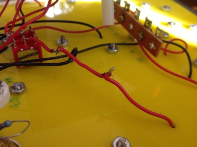
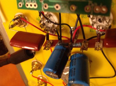
One problem may be that I accidentally severed the red wire from the left D cell and had to doctor a connection. See pic. This might be the source of the problem? Though I'm getting 1.64 volts at the end of that wire...

Do you still want me to replace batteries and recheck voltages?
 

Attachments

  • image.jpg
    image.jpg
    1,019.9 KB · Views: 143
My error - I have of course not memorized the terminal numbers of every Bottlehead product, and sometimes I guess wrong. Your batteries are fine; I mistook T7 for the full voltage which is not on the measurements list.

But that is useful information. Have you fixed the reversed-D-call manual error (sticky in this sub-forum)?

If the tube bias (A5, B5) is 0.32 volts, that is very low, and would explain the low plate voltages (A6, B6). That bias is set by the 1000 ohm resistor. It should read around 1.5-2 volts, which is the current generated by the PJCCS. The low voltage indicates something is shorting the 1000 ohm resistors, and the only candidate is the electrolytic bypass caps. As an experiment, disconnect one capacitor wire from the circuit and see if the voltages get more reasonable.

Nevertheless, this does not address the one-channel problem. So far the voltages indicate both channels are operating similarly, pointing to input or output wiring problems. Since it worked before, it is logical to suspect a questionable solder joint which got jostled, or failed for some other reason.
 
Can't test now, but will do so tomorrow. When I first had this problem I re flowed all the joints, thinking that was it. But apparently not.
 
OK, so the cap is not shorting the resistor. Let's be sure it's the right resistor then - measure resistance from ground to A5, and to B5. Both should be 1000 ohms.

Next, set your meter to DC current and connect ti between A5 and A6; you should see a bit less than 2mA. Repeat on the B socket. This is to see if the current source is supplying the desired current - I suspect it is, but as I said the voltages are not consistent with the wiring, so there is something wrong which I can't yet identify.

You have not said whether the reversed-D-cell issue was resolved - I'll need that information too, in order to determine why the voltages on the tube itself are so low.

I am still not addressing the missing channel, because I want to get the tubes operating correctly first. But I have not forgotten it!
 
Paul Joppa said:
OK, so the cap is not shorting the resistor. Let's be sure it's the right resistor then - measure resistance from ground to A5, and to B5. Both should be 1000 ohms.

Yes, they are.

Paul Joppa said:
Next, set your meter to DC current and connect ti between A5 and A6; you should see a bit less than 2mA. Repeat on the B socket. This is to see if the current source is supplying the desired current - I suspect it is, but as I said the voltages are not consistent with the wiring, so there is something wrong which I can't yet identify.

Is DC current different from voltage check? I have V, 300mV, resistance, and A as options on my Fluke. And you want me to put one lead to A5 and then the other to A6? With the power on or not?

Paul Joppa said:
You have not said whether the reversed-D-cell issue was resolved - I'll need that information too, in order to determine why the voltages on the tube itself are so low.

Yes, I've done this.
 
A is amperes, which is the unit of current. We are looking for mA, milli-amperes - I assume that's an auto-ranging meter which can read that low. Power on.

You have most recently measured about 15v at tube pin 6, and 0.3v at pin 5; the ampere measurement will short these together but it won't hurt anything. The current source should put out the right current, no matter what the voltage is.

If the measured current is low, around 0.3mA, then the current source has a problem and we'll move to measuring some voltages on it. If the current is correct (1.5-2mA) then there is something wrong that makes no sense if everything is wired correctly - so some pictures of the socket wiring will be needed.
 
No, that can't be right. I'm at a loss. I'll study the pictures and think for a while - maybe PB will join if he sees anything. Whatever it is, it's the same both sides.

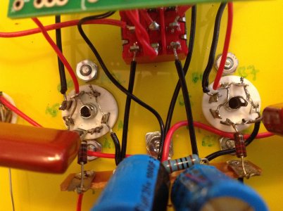
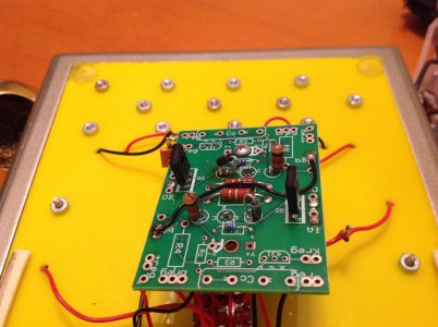
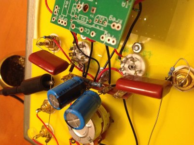
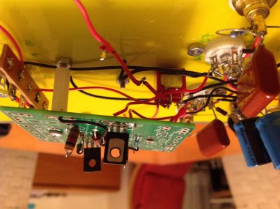
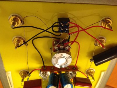
Meanwhile, could you post a picture of the PC board, and another picture of the tube sockets showing what's under the electrolytic caps?

I think it might help to see the voltage at each tube pin. Get the voltages on the PC board wires as well - bA, IA, IB, OA, OB. This is mostly to make it easier to go forward, without re-reading the thread, and to be sure nothing has changed so far. I know this is repetitive, but since it does not make sense there must be some assumption I'm making that is not true - re-checking all the available data is a starting point for that.
 
Thanks, Paul.

A1  1.7
A2  16.66
A3  0
A4  16.67
A5  0.321
A6 16.67
A7 1.7

B1 1.66
B2  16.17
B3  0
B4  16.18
B5 0.281
B6  16.18
B7 1.66

bA  0
OB  16.69
IB 34.5

bB  0
OA 16.18
IA 34.4
 
Pics
 

Attachments

  • image.jpg
    image.jpg
    1.6 MB · Views: 133
  • image.jpg
    image.jpg
    1.6 MB · Views: 137
  • image.jpg
    image.jpg
    1.4 MB · Views: 128
  • image.jpg
    image.jpg
    1.5 MB · Views: 123
  • image.jpg
    image.jpg
    1.5 MB · Views: 136
Bingo! I think I've got it.

B5 should go to the 1000 ohm bias resistor; you have the resistor going to B1/B7.

This may be my fault - I will review the notes in the sticky about the D-cell fix.

When that is fixed, you should see the pin 5 voltages make sense, and the plate voltage will increase ~10 volts, giving you more headroom in the output.

I still puzzle over the 6mA current reading, but the voltages now make sense so I speculate that was a fluke (sorry!).

==========================================

Now we can ask why you get only one channel. I think you've already done all or most of the initial easy steps, but I'll list them here for completeness:

* re-heat all the solder joints
* check the RCA jacks for tight mounting nuts
* swap channels on the input cables to prove the source has both channels
* swap channels on the output cables to prove the rest of the system has two channels
* swap the tubes to prove it's not them
* check the resistances and voltages

A clip lead is an adequate tool for the Quicky, where the voltage is low.

With a source and power amp connected, you should be able to hear the working channel. You may want to shut down the power amp between cliplead configurations.

First, clip the center lug of the input RCA on the non-working channel to the corresponding output RCA center lug. You should hear that channel (careful, it might be really loud!), proving that the RRCA jacks connect to the source and to the power amp.

Now we can check various points in the circuit. Remove the cliplead from the input RCA, and connect it to the tube-socket end of the 2.2uF output capacitor.
Nothing? go to tube pin 6.
Nothing? go to tube pin 3 (the signal will be quieter from here on out).
Nothing? go to the far end of the 220 ohm resistor that is connected to pin 3.
Nothing? go to the center terminal on the relevant section of the volume control potentiometer.
Nothing? go to the "hot" terminal of that pot section.
Nothing? Repeat the initial test to confirm everything was working.

Anytime you get something, you have located the problem to the nearest solder joint.
 
Wait, the D cell correction sticky says to wire 4L to B1/B7. Are you saying it should be wired to B5? Isn't that where the mistake in the manual said to wire it? And what about A5? And if 4L goes to B5, what goes to B1/B7? I'm confused.

EDIT: To clarify: you want me to reverse the D cell battery reversal fix?
 
Ok, switched it back to 2L/4L going to A5/B5, and the negative lead of the D cells going to A1-A7/B1-B7. This is how the manual says to do it. Certainly doesn't seem right.

Here are the new voltages:

1  -0.015
2  1.566
3  0
4  1.524
5  -0.029

6  16.09
7  24.16
8  8.03

A1  0.21
A2  14
A3  -0.013
A4  14.06
A5  1.566
A6  14.06
A7  0

B1  -0.026
B2  13.74
B3  -0.027
B4  13.74
B5  1.519
B6  13.75
B7  -0.022

I'm getting sound in the R channel. I've swapped input and output cables and tubes. I'll re-heat solder joints once we get the voltages right. Note: I accidentally left it on all night and drained the batteries, so I'm using "old" 9Vs that are measuring 8. I'll head out to buy new ones for more accurate readings, but obviously that's not the main problem.

 
GOT THE LEFT CHANNEL WORKING  ;D

Reflowed a few more L channel joints. One of them must have been the culprit.

So: now let's get back to why the voltages are off... or are they still?
 
No, it's not right. Sorry if my directions are wrong, or confusing - I have a bad flu and I'm pretty punchy the last couple weeks!

The D cell negative should go ultimately to tube pin 5. D cell positive to pins 1/7. You should see about 1.5v at pin 5, and about 3.0v at pins 1/7.

There is the switch in the way, and I'm going back to bed without figuring it out yet ... maybe tomorrow unless PB steps in, he's more familiar with the wiring, I don't have a Quickie at home.
 
Caucasian Blackplate said:
Now that it's working, you should remeasure.

Voltages are as given above, though I did switch it back to the "mistaken" manual wiring. Should I switch it back? Or just reverse the D cell?

Paul, sorry you're not well!! Hope you're better soon.
 
Back
Top