Left Channel Died

kevinlei324

New member
My left channel just randomly died. Switching the tubes didn't help.

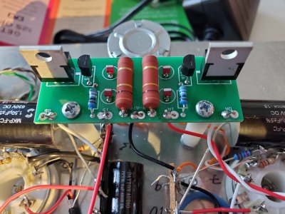
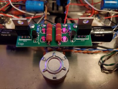
I have the C4S installed, and all the LEDs turn on.

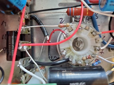
Resistance test checks out, but for voltage, 16 is measuring 4.98v.

 
What voltage do you get at pin 9 on the 12 pin socket on that side?

I suspect you either have an issue with the C4S board, the insulation on the connection to tube socket pin 11, or maybe a coupling cap issue.

Posting some photos of the area could be helpful too.
 
I attached some pictures of the area.

At pin 9, I'm getting 1.25v.
At pin 12, I'm getting -3.05v

Thanks!
 

Attachments

  • 20190820_174141.jpg
    20190820_174141.jpg
    3 MB · Views: 21
  • 20190820_174115.jpg
    20190820_174115.jpg
    2.9 MB · Views: 17
  • 20190820_174100.jpg
    20190820_174100.jpg
    3.3 MB · Views: 17
Kevin - you've probably already ruled out the problem stemming from somewhere upstream in your audio chain - but just in case you haven't: you could switch the left and right rca cables at the amp inputs (but not at the source outputs) and see if the dead channel switches sides.


cheers, Derek
 
Oops. Apologies - I missed the part about your voltage being off.
 
Thank you for the input!

I was actually thinking of investigating something in my system... My DAC goes into an RCA switch that I use to switch between multiple outputs including my speaker amp and my Mainline.

I hooked up an Emotiva amp I had laying around, and for some reason, there was a lot of static in the left channel. The system played fine for a little while but eventually tripped a fault somewhere. Now, it would only play for a few seconds before tripping a fault.

My Mainline plays flawlessly though through the RCA switch. No static or any noise... But I still can't help but wonder if something in the signal path screwing with the left channel...
 
Maybe there's something to this. I would definitely try plugging the left output into the right input of your S.E.X. amp, and vice versa. If the problem shifts to the other channel, it's definitely an upstream issue.


Edit: and/or try plugging the S.E.X. into the switch outputs you're presently using for the Mainline. Maybe it's a loose connection in the rca switchbox?


I don't have a S.E.X. amp, so I have no idea whether your posted voltage variance is a cause for concern.


cheers and good luck, Derek
 
I added more solder and heat. At first, 16 read a steady 4.85v. I prodded around a little more, checking the other leads, and suddenly, I noticed the LEDs on the right started shining much brighter. I measured the voltage again at 16 and it started reading 301v. I turned it off ASAP.


Attachments

  • 20190820_220434.jpg
    20190820_220434.jpg
    2.9 MB · Views: 16
  • 20190820_220411.jpg
    20190820_220411.jpg
    4.1 MB · Views: 15
I just heated and added solder to all the joints from leads 15 to 28, all the pins on the affected tube socket, and all the leads on the bottom of the C4S board. No luck. LEDs on right still super bright and lead 16 reading 301v.
 
16 reading 301V is a whole lot better than ~5V.  When IA and OA on a C4S measure about the same, I recommend reflowing the solder joints on the MJE5731A, especially the middle leg!
 
I reflowed all the joints. I tested the voltage for all legs (the actual component legs, not solder joints) on the MJE5731As and the components' legs they're attached to (ie left leg to LED, middle leg to OA/OB, and right leg to transistor) and the voltages correspond, so I think the joints are solid. The measurements I got are listed below, if they might be of some helpn

OA = 70.6
IA = 368

OB = 299
IB = 315

The 3 pins on the A (left) MJE5731A measure (from left to right), 364v, 70.6v, and 365v, respectively.

The 3 pins on the B (right) MJE5731A measure (from left to right), 311v, 298v, and 299v, respectively.
 
How's the voltage at pin 10 of that 12 pin socket? 

Now that the plate voltage on the driver has popped up, I would also do another tube swap.
 
Before tube swap:
10 = 0v
12 = -3.05v

After tube swap:
10 = 0
12 = -3.05

OA = 68.4v
IA = 367v

OB = 302v
IB = 318v

The 3 pins on the A (left) MJE5731A measure (from left to right), 364v, 68.4v, and 365v, respectively.

The 3 pins on the B (right) MJE5731A measure (from left to right), 314v, 301v, and 302v, respectively.
 
Alright, so you have 1.25V at pin 9, this is drawn across a 1.27K resistor, which means that 1mA of current is flowing where there should be 2mA.

1.2V of bias on the tube and 300V at the plate would indicate 40mA of current drawn based on the curves for the 6DJ7.

Either you have shorted transistors in the C4S, or you have lost the ground reference for the grid on that 6FJ7.  The grid for section 1 is pin 10 on the 12 pin socket, in is connected to pin 8 by a 220 ohm resistor, then is wired to the volume pot.  If any of those connections are loose or poorly soldered, you will lose your ground reference and your voltages will go whacky.  This can include all of the connections at the pot itself, so a broken ground wire up by the pot could cause this issue.

If you have shorted transistors on the C4S, this could be confirmed by setting your meter to measure continuity (it will beep when you touch the probes together), then check each pair of legs on each transistor on the C4S board to look for shorts.  If you find shorted transistors, then the immediate concern would be why they shorted, which would go back to a poor solder joint. 

 
The ground reference connections are good. I resoldered them anyway just to be sure. I think you're onto something with the transistors. None of the PN2907A seem to be shorted. However, the MJE5731A on the right (the affected channel) might have a problem. When set on continuity, when I test the middle and right lead, it doesn't straight beep like a real short, but i hear rapid clicking from the meter. This does not happen with the MJE5731A on the left. Could it be a bad transistor?
 
Back
Top