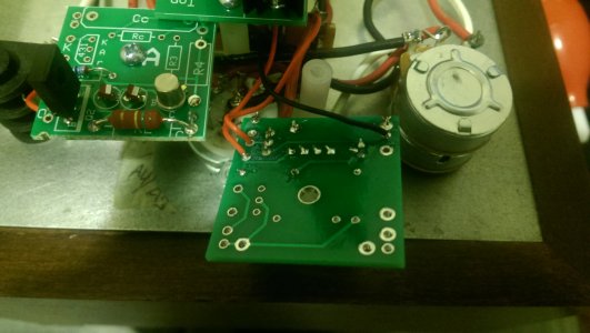
On your last photo, have a look at the solder joints on R2. One of them looks very inadequately heated.
You are using an out of date browser. It may not display this or other websites correctly.
You should upgrade or use an alternative browser.
You should upgrade or use an alternative browser.
Issue with Crack Voltage [solved]
- Thread starter lwhitit
- Start date
Caucasian Blackplate said:On your last photo, have a look at the solder joints on R2. One of them looks very inadequately heated.
I removed the old solder and cleaned everything up again but still no change. Not sure what else to do.
Attachments
You might want to try running the amp with no 6080 and with the large Speedball board removed. This will isolate the 12AU7 and the small PC boards that feed it, and may bring your voltages at T1 and T5 back into check.
-PB
-PB
Thanks for the responseCaucasian Blackplate said:You might want to try running the amp with no 6080 and with the large Speedball board removed. This will isolate the 12AU7 and the small PC boards that feed it, and may bring your voltages at T1 and T5 back into check.
-PB
Just to confirm I remove the 6080 and disconnect the large SB board (with the heatsinks). After that do I leave the originally connecting wire unconnected or how should I orientate everything after removing the big board?
Leave the wires that went to the big board poking up in the air, away from anything else.
Caucasian Blackplate said:Leave the wires that went to the big board poking up in the air, away from anything else.
Real life got in the way but I was finally able to test this out. Removing all wires to the middle pcb did regulate the voltage for #1 (75) but #5 jumped all the way to 211.
Now swap the small boards. This will either isolate the issue to one of the C4S boards, or half the circuit under them.
Caucasian Blackplate said:Now swap the small boards. This will either isolate the issue to one of the C4S boards, or half the circuit under them.
Swapping the boards: B is the bad one 211 on #1. A jumped up a bit when I swapped it 83 on #5.
Try again to reheat the center leg on the MJE-350 on the bad board. Also be 100% sure that you have the correct R1 resistor installed, as swapping one of the big board R1 resistors onto a small board will leave you with high plate voltage.
Caucasian Blackplate said:Try again to reheat the center leg on the MJE-350 on the bad board. Also be 100% sure that you have the correct R1 resistor installed, as swapping one of the big board R1 resistors onto a small board will leave you with high plate voltage.
You were right I swapped the resistors
 I triple checked this thing but sure enough. I now have 80 on #1 (bad one) and 82 on #2.
 Putting it back together and powering up now I am back to where i started but with different readings. I am going to get there.
3/4 LEDS on big board lit other 4 leds are lit but very low.
Terminal Voltage
1 75-90 (67)
2 170 (76)
3 0 (0)
4 170 (75)
5 75-90 (36)
6 0
7 100 (66)
8 0
9 100 (33)
10 0
11 0
12 0
13 170 (75)
14 0
15 185 (129)
20 0
21 206 (189)
So the issue is now on the big board?
Yes, I bet if you pull the 6080, those voltages will pop up.
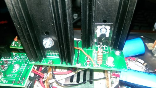
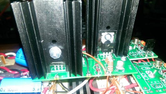
Are your TIP50's properly isolated from the heatsink with the supplied hardware?
Are your TIP50's properly isolated from the heatsink with the supplied hardware?
Caucasian Blackplate said:Yes, I bet if you pull the 6080, those voltages will pop up.
Are your TIP50's properly isolated from the heatsink with the supplied hardware?
I will check it out tonight to test. I reviewed the instructions and I did place the thermal pad (was different from instruction pic, clearish plastic looking sheet) in between the heatsinks and the tip50's. Also the fibre washer was used for each.
Terminal Voltage (6080 removed) Plus pictures of both TIP50's and heatsinks.
1 75-90 (79)
2 170 (222)
3 0 (0)
4 170 (222)
5 75-90 (81)
6 0
7 100 (1)
8 0
9 100 (0)
10 0
11 0
12 0
13 170 (222)
14 0
15 185 (228)
20 0
21 206 (233)
1 75-90 (79)
2 170 (222)
3 0 (0)
4 170 (222)
5 75-90 (81)
6 0
7 100 (1)
8 0
9 100 (0)
10 0
11 0
12 0
13 170 (222)
14 0
15 185 (228)
20 0
21 206 (233)
Attachments
Yeah, that indicates that there's either a short on the board, or the TIP50's are touching the heatsinks.
-PB
-PB
Caucasian Blackplate said:Yeah, that indicates that there's either a short on the board, or the TIP50's are touching the heatsinks.
-PB
I am not sure what to do next. Are the pics good enough to confirm if I did it correctly? If so what should I start to check on the board.
Check the resistance between the metal tab of each TIP-50 and the screw.
-PB
-PB
Caucasian Blackplate said:Check the resistance between the metal tab of each TIP-50 and the screw.
-PB
I checked it out and both look good. I get a 1 (no reading) when I check both metal tabs (silver) of the tip-50's and the connected screws.
Well, we know that the 6080 is functional, as you did pass the voltage tests with the stock circuit. Now that you have the small PC boards working, that only leaves issues with the large PC board. I would suspect that some adjacent pins are soldered together, causing the short that is dragging your voltages down.
Caucasian Blackplate said:Well, we know that the 6080 is functional, as you did pass the voltage tests with the stock circuit. Now that you have the small PC boards working, that only leaves issues with the large PC board. I would suspect that some adjacent pins are soldered together, causing the short that is dragging your voltages down.
Ok that gives me an idea what to look for. I will check out my soldiering on the big board and report back.
Thanks!
Similar threads
- Replies
- 3
- Views
- 2K