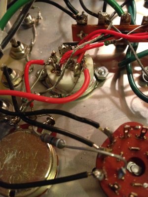
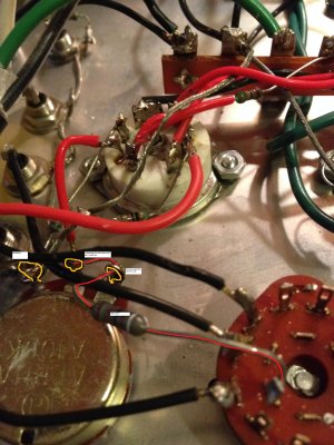
The tune up is coming along pretty good. I did place new 100k resistors across in/out of vol pot. Vol pot is now single Valab series stepped attenuator. I really like it. Vol is not twitchy like it was before.
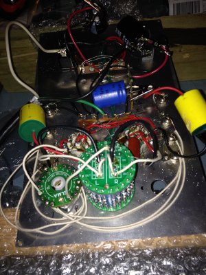
My mental state is being messed with by cap 1 and cap 2 of power supply though. I ordered 220uf as the original value spec'd. The new ones showed up measuring 190uf each. Should I let this bother me and replace them or parallel some, or it's fine and no performance issue. I mean it is foreplay but i don't want a performance issue. haha
Thanks
Eric


 DkAAOSwkNZUqwuK