High voltage during voltage check

wink

New member
Hey Bottleheads,

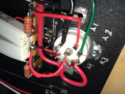
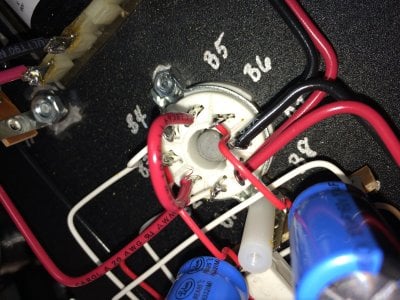
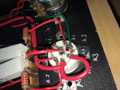
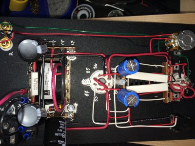
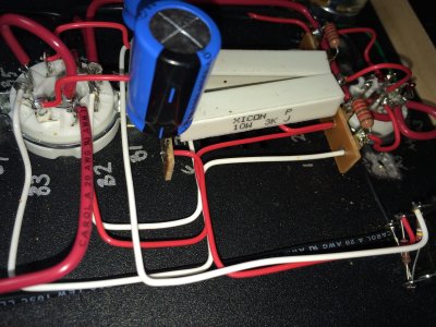
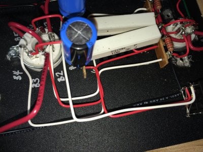
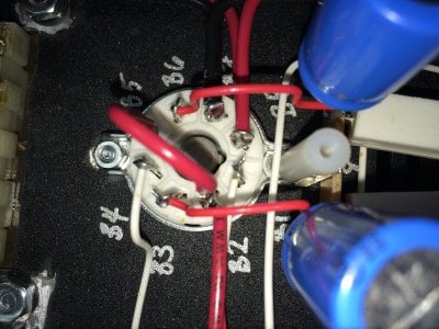
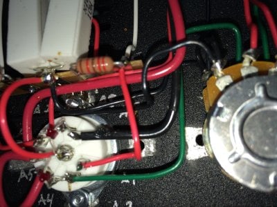
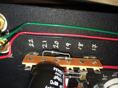
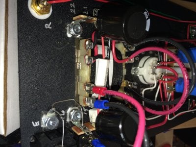
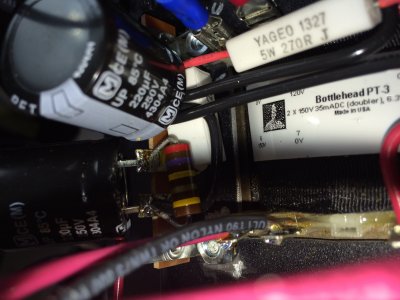
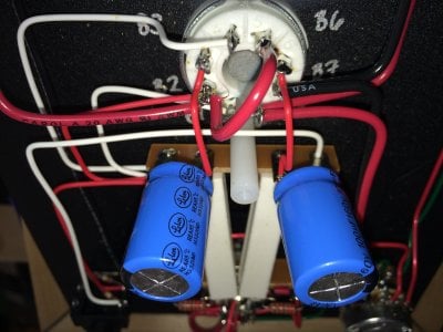
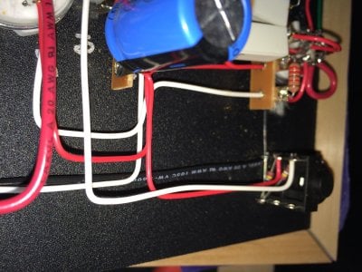
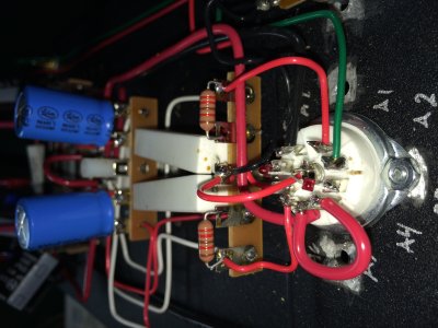
Just completed my voltage checks and 2 were off by more than the tolerance. At B1 I have 148.8v and not the 90 that is listed. B3 is 148.4 v instead of 100v. If these are acceptable voltages, could someone please explain why they are ok even tho they are above tollerance?
Thank you
 
I just triple checked. Everything seems correct on that terminal strip. I also plugged my headphones in, just to check (possibly dangerous, I know, but they were 650s and I don't like them much) and the right channel is out. Audio only through the left. I swapped cables, inputs, and source, and it's still out.
Thanks for the help
 
RW said:
I just triple checked. Everything seems correct on that terminal strip.

Did you remeasure the voltages?  As I mentioned, B1 wires to terminal 1.  If you have different voltages at B1 and terminal 1, you don't have a wire between B1 and terminal 1.

-PB
 
B1 & terminal 1 measure at 148.5v
Just noticed that the LED at A8 is out. It was on yesterday and I havent changed anything.
 
I will assume that you don't have the Speedball installed.

For high voltage at T1 and no LED on, you are most likely not heating both halves of the 12AU7.  (Can you see both halves lighting up?).  If this is the case, the red wire between A4/5 isn't properly soldered. 

-PB
 
No speedball yet. It's going in as soon as I get this straightened out.
I do see both sides of the 12au7 lit up.
I did a continuity test on multiple points on A4/5 and they were good. I reflowed some solder and checked again. Still have continuity.
I cleaned the pins of the 12au7, just to make sure
I did notice when I was doing the continuity test on A4/5, I had continuity between the chassis and A4/5. Is that ground? I went thru the instructions and wiring again to check a 4th time and everything is correct. And the LED is still out
 
RW said:
B1 & terminal 1 measure at 148.5v
Just noticed that the LED at A8 is out. It was on yesterday and I havent changed anything.

If something changed without You changing anything, then most likely there must be a flaky contact somewhere, be that a solder joint or even a short somewhere. Have more voltages changed aswell? Any way to post pictures?

And Yes, A4/5 are GND, this for reference: http://bottlehead.com/smf/index.php?topic=4812.0
 
I can post photos after work. Anything specifically? I went over the wiring and connections 4 times. I can do another voltage and continuity check later as well. The only thing that I've "changed" was plugging in a pair of headphones, and removing the tubes to turn over the unit to work on it.
 
The next step is to very, very carefully measure voltage at A7.  It should be around 0, but could be wandering around if there's a grounding issue on the left channel. 

-PB
 
Here are some photos. If there is something else that I may have missed, please let me know.

I have 0 volts at A7
 

Attachments

  • image.jpg
    image.jpg
    1.9 MB · Views: 81
  • image.jpg
    image.jpg
    2.1 MB · Views: 91
  • image.jpg
    image.jpg
    2 MB · Views: 77
  • image.jpg
    image.jpg
    2.4 MB · Views: 101
  • image.jpg
    image.jpg
    2.2 MB · Views: 82
  • image.jpg
    image.jpg
    1.3 MB · Views: 90
  • image.jpg
    image.jpg
    2.3 MB · Views: 87
  • image.jpg
    image.jpg
    2.1 MB · Views: 84
  • image.jpg
    image.jpg
    2.9 MB · Views: 84
  • image.jpg
    image.jpg
    2.1 MB · Views: 78
  • image.jpg
    image.jpg
    2.2 MB · Views: 86
  • image.jpg
    image.jpg
    2.2 MB · Views: 85
  • image.jpg
    image.jpg
    1.5 MB · Views: 82
  • image.jpg
    image.jpg
    1.6 MB · Views: 87
  • image.jpg
    image.jpg
    2.1 MB · Views: 81
  • image.jpg
    image.jpg
    1.6 MB · Views: 84
1.  When you get this running, it's going to be noisy.  The combination of untwisted heater wires and the straight input wiring is going to cause other problems for you.  (Only solved by pulling out what's there)

2.  The carbon composition resistor at the last cap is not a good idea.  It will be noisier than the resistor we provide. 

3.  The power transformer jumpers, why are they that long? Why aren't they twisted?  (Same with the A4/5 jumper)

4.  Try wiring a jumper from A3 to A8 to see if that corrects the voltage at terminal 1. (A short jumper)
 
Hey PB,

I used the carbon resistor because I was short a resistor in one of my BH kits, so I took it from the crack. I wasn't going to receive my new package of resistors for a few weeks until the smash upgrade was shipped. So I made a quick purchase off of eBay and they were the top search within spec. I can change it out.
I'll do the wire twist when I install the SB. I didn't think it would make a big difference but I'll do it.
I installed the jumper, both voltages are now within range, both channels work. The only thing that is still not working is the A8 LED. Any ideas?

Thanks for all of the help PB, Grainger, and SFP
 
You can leave the amp as-is.  Either the LED on A8 is not well connected, or it got damaged in the installation.

-PB
 
So it's safe to move forward with the speedball?
Thanks again for all the help. All of you BottleHeads kick ass
 
RW said:
So it's safe to move forward with the speedball?
Thanks again for all the help. All of you BottleHeads kick ass

Yeah, I'd run the amp over the weekend, then proceed if all is still well.

-PB
 
Grainger, I have a diode tester on my meters. I will test it to see what's up. If it is bad, I should replace it, correct? I would have to remove that jumper that PB had me add if the LED is being replaced? Thanks for the help and input.

PB, ok, I'll run it for a few days. Unfortunately I'm not a fan of my headphones that I have for it (650s) so I'll just let it run a playlist for a few hours on its own, I'll just leave the headphones in so it has a load. Thanks for the help, I certainly appreciate it
 
Back
Top