High voltage checks - help please!

OutFishing2

New member
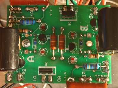
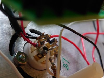
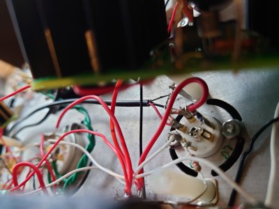
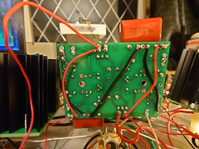
Hi, I have assembled my c2a and really enjoyed the build. I have hit a stumbling block on the voltage checks with a high result on KregA and various high voltages on all the boards. Please can I seek some help?

I will post voltage results and if it helps I can list the steps I've taken to chase down the error.

I should add I'm in UK so on 240v.

Thank you in advance!

David
 
HP: T = 0.6mv steady whilst R cycles between 20mv and 50mv

LowVoltageBoard
IA = 197 (!)
OA = 66
KregA = 12.5 (!)
BregA = 172 (!)
IB = 172 (!)
OB = 72
KregB = 6.8
BregB = 196 (!)

High VoltageBoards
        RCA side    <>    PSU side
IA          198                    194
OA        196 (!)              170 (!)
bA          0                      0
IB            0                      0         
OB        108                  103
bB        196 (!)              170 (!)       
 
Hi Paul,
Yes bridges look correctly done. Photo of my board attached for ease.
Thank you for the quick reply!
David
 

Attachments

  • 20240207_215813.JPG
    20240207_215813.JPG
    1.7 MB · Views: 13
What's the DC voltage on pin 1 of each 6AQ5 tube?  The Kreg voltages are plenty high to allow the regulator to work, but the absence of properly regulated voltages on both sides would point to some kind of repeated mistake on each side. 
 
It should not matter, but it might be worth double checking that you also see 0V at pin 7 on each 7 pin socket. 

I'd also be interested in the DC voltage present at the terminals marked X on the center C4S board, as well as a bottom shot of that center C4S board. 

I've also sometimes encountered oddball problems like this when the power supply feed going into IA is accidentally wired into OA, or the wire that's supposed to leave OA and feed the rest of the amp is instead fed from IA, though these issues are not necessarily indicated by the voltages you are reporting.
 
Hi Paul,

So pin7 on the B & D sockets are each 0v.

X at the cap legs are 3.1v, descending slowly on A side and 3.7v ascending slowly on B.

I will double check all the OA / IA leads now.
 
Power routing on the build looks as follows:

Terminal 24 to HighCurrent IA on RCA side
RCA side HighCurrent OA to terminal 6
Terminal 6 splits three ways to C2, LowCurrent IA and B5

B5 resistored to B6

LowCurrent OA to terminal 2
Terminal 2 splits two ways to A6 and C1

LowCurrent OB to A1 and C4 via terminal 4

LowCurrent IB to terminal 16
Terminal 16 splits three ways to C5, D5 and HighCurrentBoard PSU side OA
D5 resistored to D6

HighCurrentBoard PSU side IA to terminal 30


Looking over the power routing reminded me of one anomoly I noticed in the build process. I don't think it's relevant but you may know better. On p61 there's an instruction to connect a short black wire between 1U and -reg and in the photo given, there's no sign of a longer black wire which was previously attached between 1U and high current board IB. I've built it with both wires in place.
 
I would double check that the 431 regulators are in the correct spot, then resolder their connections if they are where they should be.  The 3V at X tells me that the 431 regulators aren't doing anything.  Also be extra certain that all those black jumpers on that center PC board are well soldered.
 
I've resoldered the 431 regulators. They were in the right spots. No change to X volt readings and IA and KregA are still the same as posted yesterday.

Is it worth slotting in new 431s?

David
 
I would double check that the -reg pads on the center C4S board are all reading 0V.  Typically a failed 431 will show 1.8-1.9V at the X terminal and Kreg, so what you're observing is more like a 431 that's partially disconnected (hence my initial inquiry about that jumper that's easily left off).
 
Thanks Paul.

The -reg pads on the centre C4S board are at 0v effectively, <4mV for both A & B.

I resoldered all the pins on the board for good measure and replaced the black and red wires under the board. Also fitted new wire bridges across +reg. Voltage readings are unchanged.
 
I'm still leaning towards a solder problem.  The common problems we find that prevent solid joints are insufficient heat and insufficient lead in the solder.  You want 900F/500C or so of iron temp, and 60/40 leaded solder is also extremely helpful.  Missing one of those elements will make soldering a lot more difficult than it should be.  Along with the sufficient heat, you also want enough time for the solder to flow through the PC board holes to really grab onto the component leads.  Looking at your board, you can see how this has happened with the LEDs (they have low thermal mass) but not the 431 regulators (slightly higher thermal mass). 

More info can be found here:
https://www.youtube.com/watch?v=EN16Pi7pcfk

I've been building this stuff for 25 years and I still have problematic joints here and there.
 
Yes, I appreciate that. My soldering skills have certainly got better whilst building the kit. The troubleshooting phase has given me chance to go back over the wiring around the transformer and power and it's all looking neater now.

I followed your advice and reflowed all the points on the board in the last hour except the LEDs. My iron only goes to 480'C but fairly close to what you recommend.

I had done most of the kit with the iron set at 380'C and I can see now how the extra heat creates much shinier joints. Solder is 60.40 0.7mm.

I'm still 12v on KregA, 3.xV on the X terminal.

 
It's also worth mentioning that having the wires that go to each Kreg terminal swapped can give funny consequences like this.  Same with the red wires connected to IA/IB on the center C4S board.  If one pair of those wires is swapped, the regulators will not function properly.
 
Back
Top