I think you should wait for PB's input before powering the amp again.
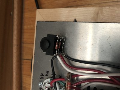
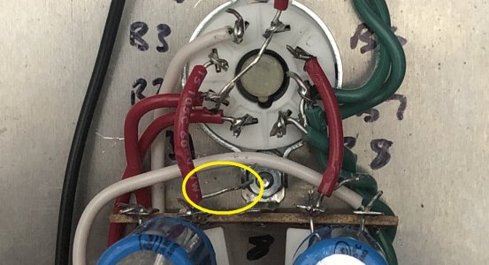
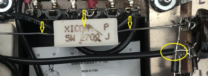
But there is one thing I would suggest doing in the interim . See circled area in the attached pic: the black wire has too much exposed wire and looks like it might be touching (or might end up touching) the lead of the diode below it. If that happens, I think you'll have a short circuit every half cycle that will draw a ton more current than the transformer and diodes are meant to handle. I suggest reheating the joint and pulling the black wire further into the solder lug so that the bare wire and the diode lead no longer overlap.
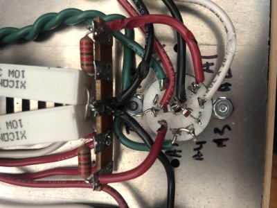
I've also indicated with arrows what look to me like signs that the first 270 ohm resistor has been overheated - this is really just to bring it to PB's attention. I'm not sure if has been overheated, or even if it has, whether this is a problem. PB will let you know.
cheers, Derek