Half of LEDs on Speedball large board not turning on.

tjames37

New member
Hello all,

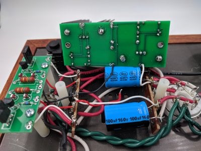
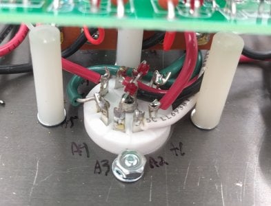
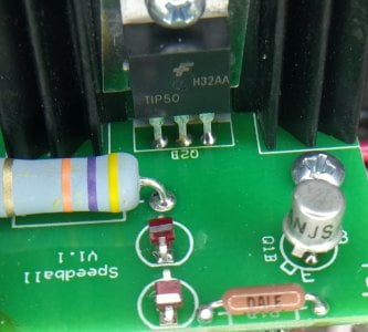
I have been using the basic crack for about 2 weeks, it has been working well. I attempted to upgrade to the speedball today. I installed the small board, did voltage checks, and everything is well. When I installed the large board the channel's LEDs closer to the transformer were not lighting. I am getting voltage between the LEDs and the 47k resistor and it fluctuates around 5V, but the LEDs do not light. I am starting to think its a bad LED. Here are my other voltages.

small board:
0A - 76V
1A - 204V
B-A/B - 0V
1B - 204V
0B - 73V

big board:
0A - 119V
0B - 173V,137V
B+ - 204V
G - 0V

Images: imgur.com/a/9At8auI

 
tjames37 said:
0B - 173V,137V
Which voltage do you get at OB on the big PC board?  One of these is a working voltage, and one is not.

I would imagine that this issue could be resolved by flipping the big PC board over and reheating all the solder joints (especially those on the TIP50 transistors).

 
As it turns out the LEDs were bad on the 0B side of the large board. I replaced the LEDs and now they light properly, i must have overcooked them. After this fix it seems that the 0B side's LEDs are lighting as soon as the amp is plugged in, but the 0A side takes about 10 seconds for the LEDs to light up. The 1B/0B side of the small boards LEDs are now not lighting either. Despite the board working properly earlier. Here are the voltages. Thoughts? Is this normal behavior?

small board:
0A - 75V
1A - 203V
B-A/B - 0V
1B - 203V
0B - 60V

big board:
0A - 113V
0B - 123V
B+ - 203V
G - 0V

Thanks!
 
tjames37 said:
As it turns out the LEDs were bad on the 0B side of the large board. I replaced the LEDs and now they light properly, i must have overcooked them. After this fix it seems that the 0B side's LEDs are lighting as soon as the amp is plugged in,
The LEDs were not the issue.  Can you post some photos of your build?  We might be able to spot the issue.  Did you resolder all of the joints on the big PC board?
 
I have re-soldered all the joints on my large board 3 times. Ignore the unsolder 0A and B+ I have been unsoldering them to work on the underside.

Thanks!
 

Attachments

  • IMG_20180420_131507.jpg
    IMG_20180420_131507.jpg
    2.8 MB · Views: 17
  • IMG_20180420_131545.jpg
    IMG_20180420_131545.jpg
    983.9 KB · Views: 9
  • IMG_20180420_131550.jpg
    IMG_20180420_131550.jpg
    1.3 MB · Views: 6
  • IMG_20180420_131902.jpg
    IMG_20180420_131902.jpg
    467.4 KB · Views: 8
  • IMG_20180420_132110.jpg
    IMG_20180420_132110.jpg
    355.2 KB · Views: 8
I think I got it figured out. I'm only reading 0.3 ohms across the collector and emitter on the 0B TIP50. Any idea where I can get another? Thanks!
 
Mouser is a good place to get them.

From the top side photo, it looks like the collector of Q2B (center pin) is not all the way soldered.  That brown-ish/yellow color on the leg is solder flux.  This joint takes a lot of heat to properly solder.
 
I did replace one of the 1/8W resistors on the small board that was no longer functioning. The voltages on the small board are normal now.

0A- 76V
1A- 206V
B-A/B- 0V
1B- 206V
0B- 73V

I replaced the transistor on the 0B but it doesnt seem to have solved anything. I did reflow all the pins on the TIP50s and ensured that the solder flowed all the way through the holes. Here are my voltages on the large board.

0A- 119V
B- 206V
G - 0V
0B - 205V

The LEDs on the 0B side are not turning on. 0B is not dropping in voltage after the board is unplugged. After about 5 minutes the voltage is still around 190. Thoughts? Thanks!
 
Caucasian Blackplate said:
From the top side photo, it looks like the collector of Q2B (center pin) is not all the way soldered.

Did you remedy this solder joint?

Your description also indicates that the connection to the 6080 cathode is basically open, so it's just floating up to a very high voltage.  This would be consistent with the solder joint I mentioned.
 
Caucasian Blackplate said:
Did you remedy this solder joint?

Yes sir. The center pin is also holding that voltage, and I did a continuity check on the center pin. I am fairly confident the center pin is soldered.
 

Attachments

  • IMG_20180426_153154.jpg
    IMG_20180426_153154.jpg
    176.1 KB · Views: 20
Another thing to check would be the wire leaving "O" on that side of the board. If it's broken, that would cause an issue like you're having potentially.
 
Back
Top