Glad this kit is coming back!

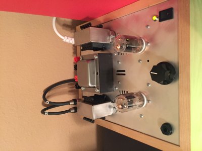
Just received my S.E.X. 3.0 via UPS!
I already have a 2.1 version w/C4S in the living room listening area and wanted another S.E.X. on my desk.

The kit came with two different brands of 6FJ7:  GE and Sylvania

I am currently sourcing additional 6FJ7s and what to have pairs of the same maunfacturer.
I would not be surprised to hear that GE, RCA, and perhaps Sylvania 6FJ7s are all made by the same manufacturer (probably GE).
I really don't expect any substantial sonic differences but I would like to have tubes with the same markings (if not only for appearance).

I remember reading in this forum that a given manufacturer of the 6DN7 tubes for the earlier S.E.X. versions should not be mixed with another manufacturer.
Can this be said for the 6FJ7 as well?

Just curious. 
 
I don't know who said not to mix 6DN7s, but that's rubbish. They all run the same in the old amp and it won't hurt anything except a case of OCD. Ditto 6FJ7s.
 
Doc B

This is where I got the idea of not mixing brands of 6DN7s:

http://bottlehead.com/smf/index.php?topic=6795.msg82645#msg82645

I used different brands of 6DN7s before.
Anyway, I may struggle against my OCD concerning matching brands!
How it sounds is what really matters.
 
Tubes are matched by manufacturer and structure. Branding is separate from manufacturer. Both tubes were made by GE. Look for the permanent dots that GE etched on the glass on all tubes they made. Also I will bet that the plate structures are the same (grey, black, or one grey one black), because your tubes were hand matched, by me.
 
I got my kit in this week and finally got around to taking a spin around the manual. Here are my observations of the improvements over previous generations that I have built.

PT10 Power Transformer. Multiple primary taps allow you to fine tune to your specific mains voltage. (115V and less, 115V to 130V) (210V to 225V, 225V to 235V, 235V to 245V)

New style heater rectifiers that mount to the top plate. This greatly simplifies assembly. The 1N5820's in the older kits were a bear to deal with sometimes. There is another nifty little trick used in the heater circuit too. No, I wont give any details. You have to buy one yourself to find out. ;)

Use of a better quality interstage cap along with a better solution for attachment.

Better layout providing more room for Parafeed caps.

CAT5 wiring for input and output wiring. I've used this type of wiring before with nice results.

All in all some very nice tweaks. There may be a few I missed too. Good job guys. I cant wait to build this.


In the middle of building one for a friend, all the changes get a thumbs up from me too.  Transformer taps are a nice touch, wired for 240v all the secondary voltage are spot on which they never were with my 2.1 as the mains here is 235-245v depending on the time of day. Heater circuit diodes are interesting, looking at the specs they have much lower reverse leakage so it will be interesting to scope the supply vs my 2.1 as i recall it had rather large spikes.  Also nice to see the PVC wiring has been replaced with the teflon coated wire, same for the cat5 in the audio path.  Interstage cap is a nice change too, as is the revised layout and grounding scheme.  Downsides, to me its not as pretty looking as the 2.1, but its a small price to pay for a quieter amplifier. Nice upgrade overall, looking forward to getting it up and running...
 
Working through the build of the 3.0 and this is the simpliest of the six BH kits I have done!

I have stopped at the heater circuit connection to the "B" side, however.

The scematic on page 6 shows that both the heater connections for "A" & "B" are the same; e.g., "A" A1 is connected to "B" B1 and "A" A12 is connected to "B" B12.
However, the directions on page 39 direct me to connect "A" A1 (Black lead) to "B" B12?!, and then "A" A12 (Red lead) is then connected to "B" B1?!
The picture matches the directions on page 39.

There is inconsistency between the scematic and the directions on page 39.
{I know most people don't follow the scematic, but it is very specific.}
Cna you explain why the tube socket heater connections are "swapped"?

I'm continuing with the build per the directions and picture.

Also, on page 54 the terminology used describing the speaker binding posts seems wrong.
The directions identify these as left and right "inputs".  These are really one of the outputs to the circuit (the other being the Headphone Jack).
Thanks

 
Interesting catch, the schematic numbering is incorrect so follow the directions/photos.  Reason being is the resistor from pin 12 to ground needs to connect to a red wire on the A side, and a black wire on the B side.
 
Thanks for the quick response.
Go PATS!!!!

edited

Here's the corrected schematic for the heater circuit:

Edited by J. Harris: please do not post schematics without permission.
 
fullheadofnothing said:
Thank you for pointing these out. I will get these corrections into the manual.
I apologize for posting the change to the schematic - I kinow better!
I just wasn't thinking this morning.
 
Just finished the resistance and voltage checks and currently listening to the S.E.X. 3.0 at my desktop.
I wired the outputs for 4 ohms.  I'm currently listneing to the amp via my laptop, Radio Tunes, through a Schiit Modi 2 DAC, feeding Klipsch R14M desktop 8 ohm speakers.  I wired this amp for 4 ohms with the intent to purchase a pair of Decware 4 ohm desktops.
This amp sounds simply fantastic with the current setup, however.
Prior to this I have been using a LM3875 Gain Clone amp at the desktop and the 3.0 has noticibly clearer and extended upper and lower registers.  The amp is very quiet.  I have listened with NAD VISO HP50 headphones and it is still very, very quiet.
Wow, this amp sounds great and I haven't even put it through any break-in.  I'm using a pair of GE Black Plate 6FJ7s.

I installed a pair of Mundorf parafeed caps and a Gold Point V47 stepped attenuator.  The Gold Point attentuator fits but I had to chisel out some space in the base to accomodate it because it came too close to the edge of the plate.

I installed a power-on indicator lamp (117VAC LED) I had used in my Gain Clone to good effect, but it didn't work with the 3.0 circuit topology. With the lamp installed the circuit would not develop enough DC voltage for the heater circuit.  So, I am left with a hole in the plate just above the power switch.

Here are some pictures:
 

Attachments

  • IMG_1945.JPG
    IMG_1945.JPG
    2.5 MB · Views: 72
  • IMG_1952.JPG
    IMG_1952.JPG
    1.2 MB · Views: 57
  • IMG_1951.JPG
    IMG_1951.JPG
    1.5 MB · Views: 45
  • IMG_1950.JPG
    IMG_1950.JPG
    2.1 MB · Views: 55
  • IMG_1949.JPG
    IMG_1949.JPG
    2.1 MB · Views: 47
  • IMG_1948.JPG
    IMG_1948.JPG
    2 MB · Views: 47
  • IMG_1947.JPG
    IMG_1947.JPG
    2.2 MB · Views: 81
  • IMG_1946.JPG
    IMG_1946.JPG
    2.3 MB · Views: 60
Seems strange that a power indicator LED on the mains side of the power transformer would pull the mains voltage down enough to affect the secondaries.
 
I haven't put my head into it yet, but I am confused about the LED, too.  I only got 0.1 VDC on the heaters.
I have a couple more of them and I'm thinking of trying it again (maybe I had a bad light).
If I do I will want to replace the power switch because I have already soldered and heated it three times.
I guess I want to have one on the side just in case.

Anyway, thanks for the great amp. A wonderfully easy build (maybe the 680 ohm resistors terminals could have been a little closer together) and absolutlely beautiful performance.
 
I see you went with the brushed metal finish on the plate chokes, very nice 8)

I have seen some LED's fail and create a short, usually when the reverse voltage is exceeded.
 
Sounds odd to me, i would have expected it to go across live and neutral.  If it is in series it would need another diode in parallel or it would block half the mains cycle.  Really need a datasheet to know what exactly is inside that unit, does it have a reversed diode in parallel, or just a current limiting resistor?
 
The link has enough of the specs to determine it should be in parallel with the power transformer primary - not in series.
 
You are absolutely right.  It should be connected in parallel.

Here's my story:
When I installed this light in the Gain Clone amp I tried the series connection and it didn't work.
I installed it in parallel and it worked as designed.

Over a year later .... I forgot about my lessons learned and tried to do it in series.  The light bulb (in my aged skull) did not come on until earlier today.

Moral of this story:  I didn't learn from my previous mistake...and...getting old is a bitch and not for sissies!

So, I put pen to paper and designed what I think is the circuit for this lamp.
I would chose a capacitor to provide the correct amount of capacitive reactance to drop a very large majority of the voltage to bring down the current to the lamp designed 4.4mA.  I would put in a resistor to handle any current spikes.
I wired the lamp directly across the primary of the main transformer.

Here is the schematic I made (nothing about this circuit should be of a proprietary nature):
 

Attachments

  • IMG_1954.JPG
    IMG_1954.JPG
    1.8 MB · Views: 100
  • IMG_1955.JPG
    IMG_1955.JPG
    1.1 MB · Views: 72
Back
Top