First time builder - failed voltage check [resolved]

shroomalistic

New member
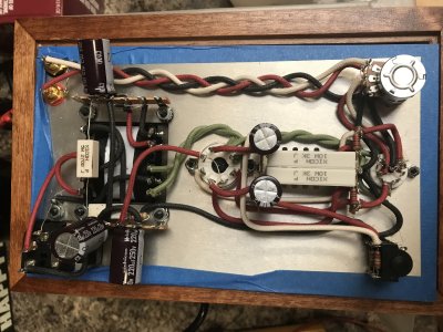
Hi guys,  having issues.  Something is definitely not right here

T01: -.9
T02: -.9
T03: 0
T04: -.9
T05: -.9
T06: 0
T07: 0
T08: 0
T09: 0
T10: 0
T11: 0
T12: 0
T13: -.9
T14: 0
T15: -.9
T16: 0
T17: 0
T18: 98.4
T19: 98.4
T20: 0
T21: 241
T22: 0

I get errors when i try to attach a picture
 

Attachments

  • IMG_3030.jpg
    IMG_3030.jpg
    2.5 MB · Views: 24
Paul Birkeland said:
Terminals 15 and 21 are connected with a 270 ohm resistor. One end of that resistor is loose or poorly soldered.

I thought there was something wrong with that resistor,  its dead.  solders are great on it,  it got super hot and i burnt my finger on it.
 
That resistor will only die if there's a catastrophic short, which should show up in your resistance checks.  Just buying another one and replacing it will lead to more dead resistors.  Is the other 270 ohm resistor in-tact?  Usually that is the one that fails first.

Is that black wire that's supposed to go to 14U going to 15U instead?  How were your resistance checks?
 
Are pins 1 and 2 touching on the 9 pin socket?

Having both resistors burnt means that your resistances at terminals 2, 4, B2, and B5 should not measure correctly.  Can you let me know what resistance values you get at those terminals?
 
it does nothing when i measure between 12u and 2,4,b2, b5.  man i hope im not reading my meter wrong.  does the * in the manual mean there should be no resistance?

a1,and a2 dont touch  pretty close but there is room for movement and still not connect
 
No resistance would be 0 Ohms, which would be a short.  If your meter says "OL", that would mean infinite resistance, which is desired.

For the resistors to go from 270 ohms to open without the cement housing cooking and falling off means they were shorted to ground, so this issue has to be found before replacing them. This doesn't happen on its own without a cause.
 
would the cap being reversed do that,  i had the wrong cap on 14u, 15u.  didnt realize it they were all different.  I then switched it with the right one and put it in backwards but I thought i caught it before powering up
 
Just to clarify the electrolytic caps aren't all different. There are just two values supplied in the kit. The caps in the power supply around the power transformer are three 220uF 250V capacitors and the output coupling caps by the 6080 socket are two 100uF 160V capacitors.

Once power has been applied to a power supply filter cap that has been installed backwards it has been stressed to a point that it should probably be replaced even if it still seems functional.
 
so i should buy new caps too?

Sorry,  Im completely blind in one eye and a my other is going bad from old age.  Its making this a real challenge for me even with magnifying glass

do you have suggestions on where to buy the parts?
 
got the new parts in,  things are still off

T01: 84
T02: 215
T03: 0
T04: 213
T05: 196
T06: 0
T07: 122
T08: 0
T09: 195
T10: 0

i replaces all the caps at the power supply side and both wirewound resistors

LED's are not lighting also
 
You kind of have to have one LED lit to have 84V at terminal 1.

The 196V at terminal 5 means that either the solder joint at A4/A5 isn't well soldered (which will cause one side of the 12AU7 not to glow) or the LED is open (this can happen from too much heat during soldering/resoldering).  Posting your DC voltages at A3 and A8 can help clarify which problem you have. 

The voltage issue at terminal 9 is an odd one and has me wondering if the octal socket is oriented properly (looks good in your photo) or possibly if the plastic keyway is snapped off of the 6080 tube.  If they keyway isn't broken, it could still be shoved in really hard and be off two pins which would short pins 5 and 6 together on the octal socket and provide the voltage issue you're experiencing.


Pull the 6080 and recheck the voltage at terminal 9 to let us know if it changes with no 6080.

You can't have 0V at A3 and A8 and 84V at terminal 1.  If your meter isn't auto ranging and it only has a higher voltage DC ranges, then it may not be able to resolve the ~1.5V or so that should appear at both A3 and A8.

Still, the 0V would tend to indicate a soldering issue at A4/A5.

 
With 6080 out,  i get 0v at terminal 9

I can try to reflow a4 and a5, but when i test them I get the same 3.2v at each

let me know if you need pictures of anything to help.
 
Back
Top