finished stereomour II amp

Smoses01

New member
Hello, I have a completed stereomour II amp I am trying to troubleshoot. Initially, I had B+ voltage on one side only. I reviewed my connections and re-heated and added a bit more solder to connections that looked not too secure. Now, I have no B+ power to either of the large tubes.
Also, I notice that the LEDs aren't lighting on the Cs4 board. I have gone over everything and cannot find the problem. My next step seems to be returning the unit to Bottlehead for repair. I thought I would try the forum before doing that. My resistance checks were all ok, and my voltages when testing the power supply were all normal. Any suggestions?
 
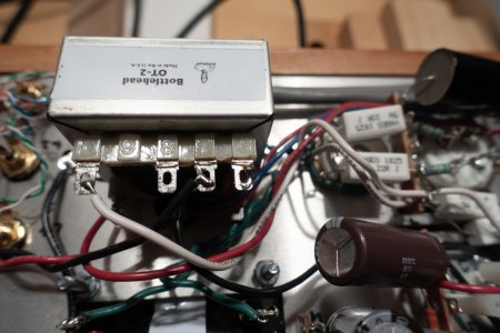
no blown fuse. I think the problem may be with where 130 2 W resistors connect together right before B+ power occurs on circuit diagram. Will post some photos. I certainly don't want to take step of sending unit back to Washington state unless absolutely necessary!
 
_MG_4553 copy.jpg

Trying to post an image of where I think problem is occurring. not sure if copy of jpeg has posted correctly, but here is a link:

/Users/stephenmoses/Pictures/Photos Library.photoslibrary/originals/D/D6A28395-3008-45CC-9D61-28F3D0E8E67D.jpeg
 
To attach  a photo, click on the "Attachments and other options" just below the text box. Note the list of acceptable file formats and the maximum size. PNG files are acceptable.
 
Today I have reviewed every joint in my build. Re-heated questionable connections, and added a bit more solder where needed. I also performed the primary and secondary voltage test on the power supply ((all were normal).
Resistance tests all good. But when go to do voltage tests, I am getting no high voltage at all. I start at the top, getting AC 120 coming in from the plug to the first small circuit board with 45, 46’ 47, 48 terminals. Then I check dc voltage at the ultrafast rectifier and get weird readings like -1.85 or such. I keep moving towards the front of kit and check every spot where B+ high voltage should be occurring, and instead of 388 volts I once again get a weird readout like -1.85.
Then going directly to the 2A3 tube sockets I get similar( -) voltages. Also, as before, LEDs on circuit board are not glowing. A few days ago I removed the circuit board, checked for proper soldering connections and re-installed it.
I really don’t want to have to return my unit to Washington state, but I am lost as what to do next. BTW, I am using a good quality meter- a Fluke 177. Stephen Moses.
 
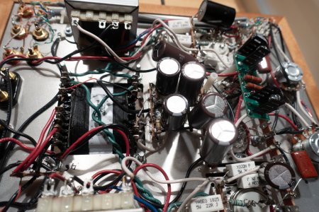
Don't worry yet - we have a good record of resolving problems like this through the Forum. It just takes a little time to be methodical. You have the attention of the guy who did the mechanical layout of the SII (and our chief technician) PB, as well as the circuit designer (myself). Photos of the build are usually a big help; be sure to include the area of the UF4007 rectifiers.
 
I'll go through these 1 at a time.


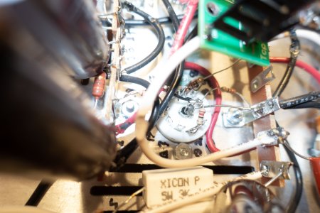
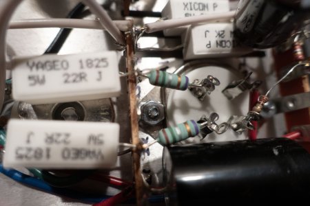
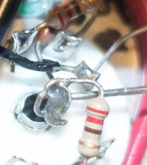
In this photo, there are several problems.  The wire going to pin 9 on the tube socket isn't routed properly and is potentially touching the resistor leaving the center post of the socket.  If this happens, you're likely going to smoke the power transformer.

The resistor going from the center post to pin 8 on the tube socket isn't properly routed and is extremely likely to cause operational issues with the amplifier. 

The tinned buss wire going to the center post needs to be routed right between pins 1 and 9 right in the middle. 

I would review how these components and wires are routed in the manual and make corrections where possible.  If it touches pin 9, that will damage your power transformer.  If it touches pin 1, that could damage your C4S board.
 

Attachments

  • steremour 1.jpg
    steremour 1.jpg
    45.9 KB · Views: 18
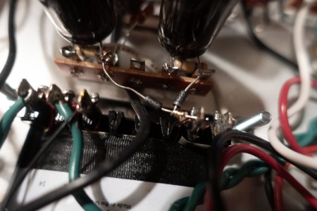
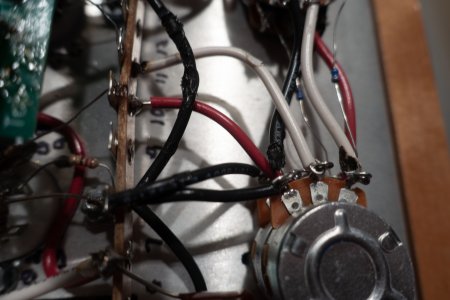
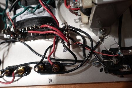
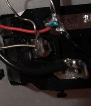
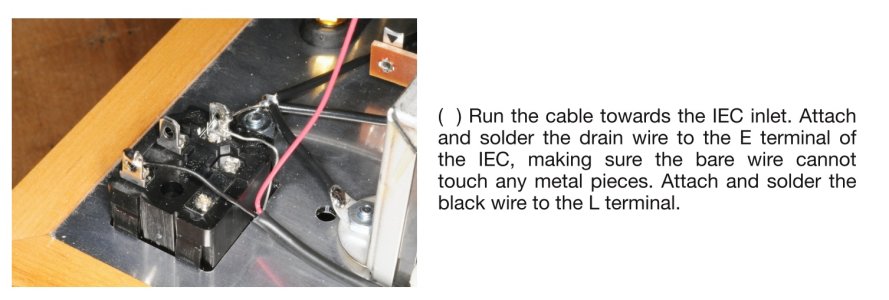
In this AC input wire, the foil shield on this shielded twisted pair wiring is earthed to the chassis.  The metal strip on the IEC power entry module that it looks to be touching carries 120V AC.  If these two touch, you will constantly blow fuses.

I have attached the photo from the manual of what's desired.
 

Attachments

  • steremour 2.jpg
    steremour 2.jpg
    43.9 KB · Views: 17
  • stereomour 2a.jpg
    stereomour 2a.jpg
    169.1 KB · Views: 14
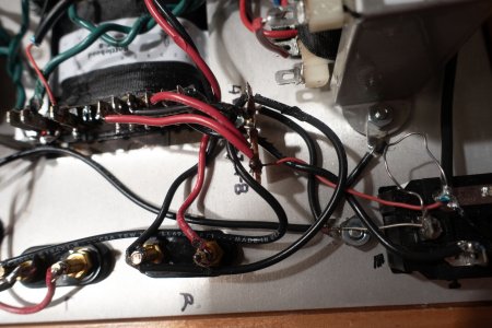
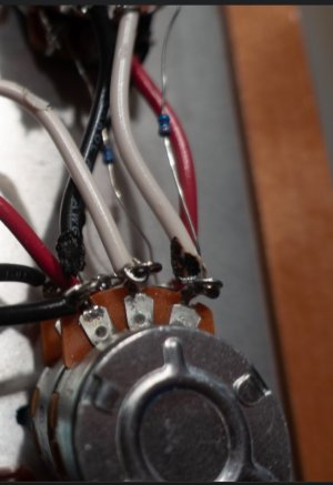
Can you carefully measure the voltage between terminals 41 and 44?

I would suspect blowing fuses should happen based on the photos, but if you are getting proper AC voltages coming out of the power transformer, you should see about 400V appearing between 41 and 44.  If you have that voltage there, but it's not making it out of there, then there's going to be a soldering issue or a missing wire.
 
Back
Top